Flow stresses occur when a mass of flowing fluid induces a dynamic pressure on a conduit wall. The force of the fluid striking the wall acts as the load.
Stress
In mechanics and materials science, stress (represented by a lowercase Greek letter sigma – σ) is a physical quantity that expresses the internal forces that neighbouring particles of a continuous material exert on each other, while strain is the measure of the deformation of the material which is not a physical quantity.
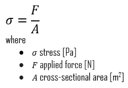
Although it is impossible to measure the intensity of this stress, the external load and the area to which it is applied can be measured. Stress (σ) can be equated to the load per unit area or the force (F) applied per cross-sectional area (A) perpendicular to the force as:
When a metal is subjected to a load (force), it is distorted or deformed, no matter how strong the metal or light the load. If the load is small, the distortion will probably disappear when the load is removed. The intensity, or degree, of distortion is known as strain. A deformation is called elastic deformation, if the stress is a linear function of strain. In other words, stress and strain follows Hooke’s law. Beyond the linear region, stress and strain show nonlinear behavior. This inelastic behavior is called plastic deformation.
Stress is the internal resistance, or counterfource, of a material to the distorting effects of an external force or load. These counterforces tend to return the atoms to their normal positions. The total resistance developed is equal to the external load.
Flow Stress
Flow stresses occur when a mass of flowing fluid induces a dynamic pressure on a conduit wall. The force of the fluid striking the wall acts as the load. This type of stress may be applied in an unsteady fashion when flow rates fluctuate. Water hammer is an example of a transient flow stress. A Water hammer in pipe or tube is a pressure spike caused by sudden variation of flow rate. and velocity energy is converted to pressure energy.
References:
Materials Science:
U.S. Department of Energy, Material Science. DOE Fundamentals Handbook, Volume 1 and 2. January 1993.
U.S. Department of Energy, Material Science. DOE Fundamentals Handbook, Volume 2 and 2. January 1993.
William D. Callister, David G. Rethwisch. Materials Science and Engineering: An Introduction 9th Edition, Wiley; 9 edition (December 4, 2013), ISBN-13: 978-1118324578.
Eberhart, Mark (2003). Why Things Break: Understanding the World by the Way It Comes Apart. Harmony. ISBN 978-1-4000-4760-4.
Gaskell, David R. (1995). Introduction to the thermodynamics of Materials (4th ed.). Taylor and Francis Publishing. ISBN 978-1-56032-992-3.
González-Viñas, W. & Mancini, H.L. (2004). An Introduction to Materials Science. Princeton University Press. ISBN 978-0-691-07097-1.
Ashby, Michael; Hugh Shercliff; David Cebon (2007). Materials: engineering, science, processing and design (1st ed.). Butterworth-Heinemann. ISBN 978-0-7506-8391-3.
J. R. Lamarsh, A. J. Baratta, Introduction to Nuclear Engineering, 3d ed., Prentice-Hall, 2001, ISBN: 0-201-82498-1.
See above:
Strength
We hope, this article, Flow Stress – Materials, helps you. If so, give us a like in the sidebar. Main purpose of this website is to help the public to learn some interesting and important information about materials and their properties.
In materials science, stress (σ) can be equated to the load per unit area or the force (F) applied per cross-sectional area (A) perpendicular to the force.
In mechanics and materials science, stress (represented by a lowercase Greek letter sigma – σ) is a physical quantity that expresses the internal forces that neighbouring particles of a continuous material exert on each other, while strain is the measure of the deformation of the material which is not a physical quantity.
Although it is impossible to measure the intensity of this stress, the external load and the area to which it is applied can be measured. Stress (σ) can be equated to the load per unit area or the force (F) applied per cross-sectional area (A) perpendicular to the force as:
When a metal is subjected to a load (force), it is distorted or deformed, no matter how strong the metal or light the load. If the load is small, the distortion will probably disappear when the load is removed. The intensity, or degree, of distortion is known as strain. A deformation is called elastic deformation, if the stress is a linear function of strain. In other words, stress and strain follows Hooke’s law. Beyond the linear region, stress and strain show nonlinear behavior. This inelastic behavior is called plastic deformation.
Stress is the internal resistance, or counterfource, of a material to the distorting effects of an external force or load. These counterforces tend to return the atoms to their normal positions. The total resistance developed is equal to the external load.
Types of Stress
Stresses occur in any material that is subject to a load or any applied force. There are many types of stresses, but they can all be generally classified in one of six categories:
Structural stresses are stresses produced in structural members because of the weights they support. The weights provide the loadings. These stresses are found in building foundations and frameworks, as well as in machinery parts.
Residual stresses are stresses caused by manufacturing processes. This type od stress remains in a solid material after the original cause of the stresses has been removed. For example, welding leaves residual stresses in the metals welded. Heat from welding may cause localized expansion, which is taken up during welding by either the molten metal or the placement of parts being welded.
Pressure stresses are stresses induced in vessels containing pressurized materials. The loading is provided by the same force producing the thermodynamics/thermodynamic-properties/what-is-pressure-physics/”>pressure. In a reactor facility, the reactor vessel is a prime example of a pressure vessel. One safety issue that is a long-term problem brought on by the aging of nuclear facilities is pressurized thermal shock (PTS). PTS is the shock experienced by a thick-walled vessel due to the combined stresses from a rapid temperature and/or pressure change.
Thermal stresses exist whenever temperature gradients are present in a material. Different thermodynamics/thermodynamic-properties/what-is-temperature-physics/”>temperatures produce different expansions and subject materials to internal stress. This type of stress is particularly noticeable in mechanisms operating at high temperatures that are cooled by a cold fluid. One safety issue that is a long-term problem brought on by the aging of nuclear facilities is pressurized thermal shock (PTS). PTS is the shock experienced by a thick-walled vessel due to the combined stresses from a rapid temperature and/or pressure change.
Flow stresses occur when a mass of flowing fluid induces a dynamic pressure on a conduit wall. The force of the fluid striking the wall acts as the load. This type of stress may be applied in an unsteady fashion when flow rates fluctuate. Water hammer is an example of a transient flow stress. A Water hammer in pipe or tube is a pressure spike caused by sudden variation of flow rate. and velocity energy is converted to pressure energy.
Fatigue stresses. Fatique is the weakening of a material caused by cyclic loading that results in progressive and localized structural damage and the growth of cracks. Once a crack has initiated, each loading cycle will grow the crack a small amount, The stresses could be due to vibration or thermal cycling.
Applied Stress
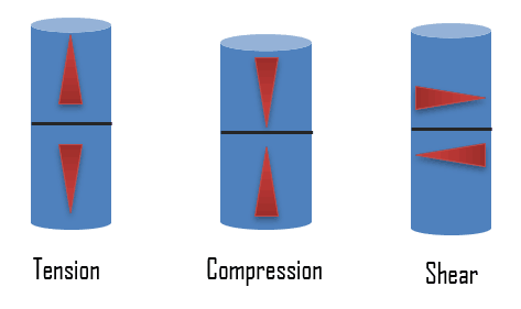
From internal point of view, stress intensity within the body of a component is expressed as one of three basic types of internal load, namely, tension, compression, and shear. In engineering practice many loads are torsional rather than pure shear. Mathematically, there are only two types of internal load because tensile and compressive stress may be regarded as the positive and negative versions of the same type of normal loading.
Tensile stress. One of the most common mechanical stress–strain tests is performed in tension. Tensile stress is that type of stress in which the two sections of material on either side of a stress plane tend to pull apart or elongate. The capacity of a material or structure to withstand loads tending to elongate is known as ultimate tensile strength (UTS). Ultimate tensile strength is measured by the maximum stress that a material can withstand while being stretched or pulled before breaking. In the study of strength of materials, tensile strength, compressive strength, and shear strength can be analyzed independently. Because tensile and compressive loads produce stresses that act across a plane, in a direction perpendicular (normal) to the plane, tensile and compressive stresses are called normal stresses.
Compressive stress. Compressive stress is the reverse of tensile stress. Adjacent parts of the material tend to press against each other through a typical stress plane. Compressive stress to bars, columns, etc. leads to shortening. Compressive stress is defined in the same way as the tensile stress but it has negative values so as to express the compression since delta L has the opposite direction. One can increase the compressive stress until compressive strength is reached. Then materials will react with ductile behaviour or with fracture in case of brittle materials. Because tensile and compressive loads produce stresses that act across a plane, in a direction perpendicular (normal) to the plane, tensile and compressive stresses are called normal stresses. The ability of a material to react to compressive stress or pressure is called compressibility.
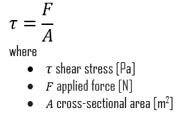
Shear stress. Shear stress exists when two parts of a material tend to slide across each other in any typical plane of shear upon application of force parallel to that plane. Torsion is a variation of pure shear in which a structural member is twisted. Torsional forces produce a rotational motion about the longitudinal axis of one end of the member relative to the other end. Shear stress is also of great importance in nature, being intimately related to the downslope movement of earth materials (as in case of avalanches).
References:
Materials Science:
U.S. Department of Energy, Material Science. DOE Fundamentals Handbook, Volume 1 and 2. January 1993.
U.S. Department of Energy, Material Science. DOE Fundamentals Handbook, Volume 2 and 2. January 1993.
William D. Callister, David G. Rethwisch. Materials Science and Engineering: An Introduction 9th Edition, Wiley; 9 edition (December 4, 2013), ISBN-13: 978-1118324578.
Eberhart, Mark (2003). Why Things Break: Understanding the World by the Way It Comes Apart. Harmony. ISBN 978-1-4000-4760-4.
Gaskell, David R. (1995). Introduction to the thermodynamics of Materials (4th ed.). Taylor and Francis Publishing. ISBN 978-1-56032-992-3.
González-Viñas, W. & Mancini, H.L. (2004). An Introduction to Materials Science. Princeton University Press. ISBN 978-0-691-07097-1.
Ashby, Michael; Hugh Shercliff; David Cebon (2007). Materials: engineering, science, processing and design (1st ed.). Butterworth-Heinemann. ISBN 978-0-7506-8391-3.
J. R. Lamarsh, A. J. Baratta, Introduction to Nuclear Engineering, 3d ed., Prentice-Hall, 2001, ISBN: 0-201-82498-1.
See above:
Strength
We hope, this article, Stress in Materials Science, helps you. If so, give us a like in the sidebar. Main purpose of this website is to help the public to learn some interesting and important information about materials and their properties.
Stress intensity within the body of a component is expressed as one of three basic types of internal load, namely, tension, compression, and shear. Types of Stress in Materials
Types of Stress
Stresses occur in any material that is subject to a load or any applied force. There are many types of stresses, but they can all be generally classified in one of six categories:
Structural stresses are stresses produced in structural members because of the weights they support. The weights provide the loadings. These stresses are found in building foundations and frameworks, as well as in machinery parts.
Residual stresses are stresses caused by manufacturing processes. This type od stress remains in a solid material after the original cause of the stresses has been removed. For example, welding leaves residual stresses in the metals welded. Heat from welding may cause localized expansion, which is taken up during welding by either the molten metal or the placement of parts being welded.
Pressure stresses are stresses induced in vessels containing pressurized materials. The loading is provided by the same force producing the thermodynamics/thermodynamic-properties/what-is-pressure-physics/”>pressure. In a reactor facility, the reactor vessel is a prime example of a pressure vessel. One safety issue that is a long-term problem brought on by the aging of nuclear facilities is pressurized thermal shock (PTS). PTS is the shock experienced by a thick-walled vessel due to the combined stresses from a rapid temperature and/or pressure change.
Thermal stresses exist whenever temperature gradients are present in a material. Different thermodynamics/thermodynamic-properties/what-is-temperature-physics/”>temperatures produce different expansions and subject materials to internal stress. This type of stress is particularly noticeable in mechanisms operating at high temperatures that are cooled by a cold fluid. One safety issue that is a long-term problem brought on by the aging of nuclear facilities is pressurized thermal shock (PTS). PTS is the shock experienced by a thick-walled vessel due to the combined stresses from a rapid temperature and/or pressure change.
Flow stresses occur when a mass of flowing fluid induces a dynamic pressure on a conduit wall. The force of the fluid striking the wall acts as the load. This type of stress may be applied in an unsteady fashion when flow rates fluctuate. Water hammer is an example of a transient flow stress. A Water hammer in pipe or tube is a pressure spike caused by sudden variation of flow rate. and velocity energy is converted to pressure energy.
Fatigue stresses. Fatique is the weakening of a material caused by cyclic loading that results in progressive and localized structural damage and the growth of cracks. Once a crack has initiated, each loading cycle will grow the crack a small amount, The stresses could be due to vibration or thermal cycling.
Applied Stress
From internal point of view, stress intensity within the body of a component is expressed as one of three basic types of internal load, namely, tension, compression, and shear. In engineering practice many loads are torsional rather than pure shear. Mathematically, there are only two types of internal load because tensile and compressive stress may be regarded as the positive and negative versions of the same type of normal loading.
Tensile stress. One of the most common mechanical stress–strain tests is performed in tension. Tensile stress is that type of stress in which the two sections of material on either side of a stress plane tend to pull apart or elongate. The capacity of a material or structure to withstand loads tending to elongate is known as ultimate tensile strength (UTS). Ultimate tensile strength is measured by the maximum stress that a material can withstand while being stretched or pulled before breaking. In the study of strength of materials, tensile strength, compressive strength, and shear strength can be analyzed independently. Because tensile and compressive loads produce stresses that act across a plane, in a direction perpendicular (normal) to the plane, tensile and compressive stresses are called normal stresses.
Compressive stress. Compressive stress is the reverse of tensile stress. Adjacent parts of the material tend to press against each other through a typical stress plane. Compressive stress to bars, columns, etc. leads to shortening. Compressive stress is defined in the same way as the tensile stress but it has negative values so as to express the compression since delta L has the opposite direction. One can increase the compressive stress until compressive strength is reached. Then materials will react with ductile behaviour or with fracture in case of brittle materials. Because tensile and compressive loads produce stresses that act across a plane, in a direction perpendicular (normal) to the plane, tensile and compressive stresses are called normal stresses. The ability of a material to react to compressive stress or pressure is called compressibility.
Shear stress. Shear stress exists when two parts of a material tend to slide across each other in any typical plane of shear upon application of force parallel to that plane. Torsion is a variation of pure shear in which a structural member is twisted. Torsional forces produce a rotational motion about the longitudinal axis of one end of the member relative to the other end. Shear stress is also of great importance in nature, being intimately related to the downslope movement of earth materials (as in case of avalanches).
References:
Materials Science:
U.S. Department of Energy, Material Science. DOE Fundamentals Handbook, Volume 1 and 2. January 1993.
U.S. Department of Energy, Material Science. DOE Fundamentals Handbook, Volume 2 and 2. January 1993.
William D. Callister, David G. Rethwisch. Materials Science and Engineering: An Introduction 9th Edition, Wiley; 9 edition (December 4, 2013), ISBN-13: 978-1118324578.
Eberhart, Mark (2003). Why Things Break: Understanding the World by the Way It Comes Apart. Harmony. ISBN 978-1-4000-4760-4.
Gaskell, David R. (1995). Introduction to the thermodynamics of Materials (4th ed.). Taylor and Francis Publishing. ISBN 978-1-56032-992-3.
González-Viñas, W. & Mancini, H.L. (2004). An Introduction to Materials Science. Princeton University Press. ISBN 978-0-691-07097-1.
Ashby, Michael; Hugh Shercliff; David Cebon (2007). Materials: engineering, science, processing and design (1st ed.). Butterworth-Heinemann. ISBN 978-0-7506-8391-3.
J. R. Lamarsh, A. J. Baratta, Introduction to Nuclear Engineering, 3d ed., Prentice-Hall, 2001, ISBN: 0-201-82498-1.
See above:
Strength
We hope, this article, Types of Stress in Materials, helps you. If so, give us a like in the sidebar. Main purpose of this website is to help the public to learn some interesting and important information about materials and their properties.
This article describes the different regions of the stress-strain curve and the importance of several specific locations. Stress-strain Curve – Stress-strain Diagram
Strength of materials basically considers the relationship between the external loads applied to a material and the resulting deformation or change in material dimensions. In designing structures and machines, it is important to consider these factors, in order that the material selected will have adequate strength to resist applied loads or forces and retain its original shape. Strength of a material is its ability to withstand this applied load without failure or plastic deformation.
However, we must note that the load which will deform a small component, will be less than the load to deform a larger component of the same material. Therefore, the load (force) is not a suitable term to describe strength. Instead, we can use the force (load) per unit of area (σ = F/A), called stress, which is constant (until deformation occurs) for a given material regardless of size of the component part. In this concept, strain is also very important variable, since it defines the deformation of an object. In summary, the mechanical behavior of solids is usually defined by constitutive stress-strain relations. A deformation is called elastic deformation, if the stress is a linear function of strain. In other words, stress and strain follows Hooke’s law. Beyond the linear region, stress and strain show nonlinear behavior. This inelastic behavior is called plastic deformation.
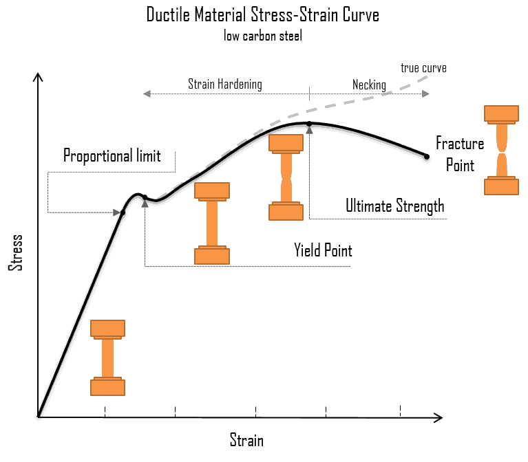
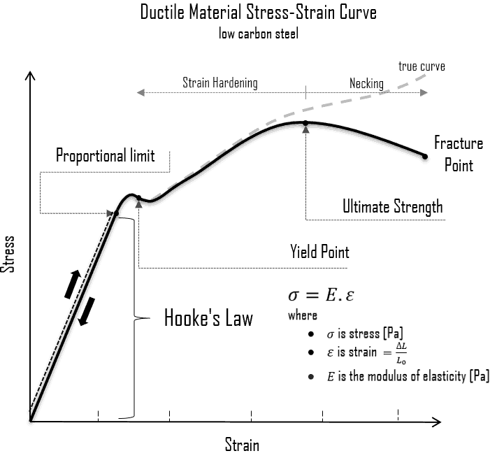
A schematic diagram for the stress-strain curve of low carbon steel at room temperature is shown in the figure. There are several stages showing different behaviors, which suggests different mechanical properties. To clarify, materials can miss one or more stages shown in the figure, or have totally different stages. In this case we have to distinguish between stress-strain characteristics of ductile and brittle materials. The following points describe the different regions of the stress-strain curve and the importance of several specific locations.
Proportional limit. The proportional limit corresponds to the location of stress at the end of the linear region, so the stress-strain graph is a straight line, and the gradient will be equal to the elastic modulus of the material. For tensile and compressive stress, the slope of the portion of the curve where stress is proportional to strain is referred to as Young’s modulus and Hooke’s Law applies. Between the proportional limit and the yield point the Hooke’s Law becomes questionable between and strain increases more rapidly.
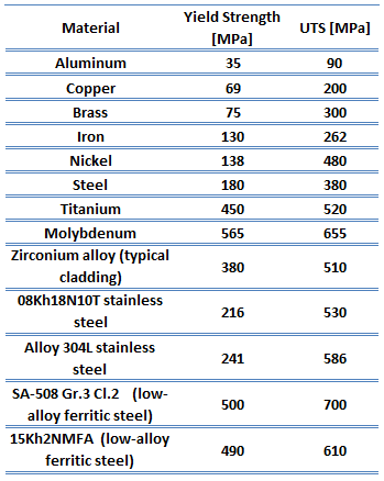
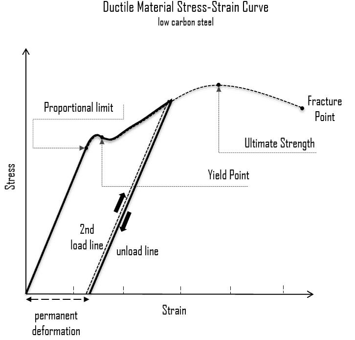
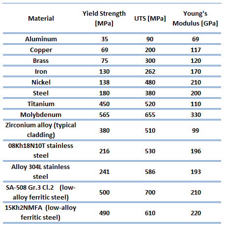
Yield point. The yield point is the point on a stress-strain curve that indicates the limit of elastic behavior and the beginning plastic behavior. Yield strength or yield stress is the material property defined as the stress at which a material begins to deform plastically whereas yield point is the point where nonlinear (elastic + plastic) deformation begins. Prior to the yield point, the material will deform elastically and will return to its original shape when the applied stress is removed. Once the yield point is passed, some fraction of the deformation will be permanent and non-reversible. Some steels and other materials exhibit a behaviour termed a yield point phenomenon. Yield strengths vary from 35 MPa for a low-strength aluminum to greater than 1400 MPa for very high-strength steels.
Ultimate tensile strength. The ultimate tensile strength is the maximum on the engineering stress-strain curve. This corresponds to the maximum stress that can be sustained by a structure in tension. Ultimate tensile strength is often shortened to “tensile strength” or even to “the ultimate.” If this stress is applied and maintained, fracture will result. Often, this value is significantly more than the yield stress (as much as 50 to 60 percent more than the yield for some types of metals). When a ductile material reaches its ultimate strength, it experiences necking where the cross-sectional area reduces locally. The stress-strain curve contains no higher stress than the ultimate strength. Even though deformations can continue to increase, the stress usually decreases after the ultimate strength has been achieved. It is an intensive property; therefore its value does not depend on the size of the test specimen. However, it is dependent on other factors, such as the preparation of the specimen, the presence or otherwise of surface defects, and the temperature of the test environment and material. Ultimate tensile strengths vary from 50 MPa for an aluminum to as high as 3000 MPa for very high-strength steels.
Fracture point: The fracture point is the point of strain where the material physically separates. At this point, the strain reaches its maximum value and the material actually fractures, even though the corresponding stress may be less than the ultimate strength at this point. Ductile materials have a fracture strength lower than the ultimate tensile strength (UTS), whereas in brittle materials the fracture strength is equivalent to the UTS. If a ductile material reaches its ultimate tensile strength in a load-controlled situation, it will continue to deform, with no additional load application, until it ruptures. However, if the loading is displacement-controlled, the deformation of the material may relieve the load, preventing rupture.
In many situations, the yield strength is used to identify the allowable stress to which a material can be subjected. For components that have to withstand high pressures, such as those used in pressurized water reactors (PWRs), this criterion is not adequate. To cover these situations, the maximum shear stress theory of failure has been incorporated into the ASME (The American Society of Mechanical Engineers) Boiler and Pressure Vessel Code, Section III, Rules for Construction of Nuclear Pressure Vessels. This theory states that failure of a piping component occurs when the maximum shear stress exceeds the shear stress at the yield point in a tensile test.
Ductile vs. Brittle – Stress-strain curves
Some materials break very sharply, without plastic deformation, in what is called a brittle failure. Others, which are more ductile, including most metals, experience some plastic deformation and possibly necking before fracture. It is possible to distinguish some common characteristics among the stress–strain curves of various groups of materials. On this basis, it is possible to divide materials into two broad categories; namely:
Ductile Materials. Ductility is the ability of a material to be elongated in tension. Ductile material will deform (elongate) more than brittle material. Ductile materials show large deformation before fracture. In ductile fracture, extensive plastic deformation (necking) takes place before fracture. Ductile fracture (shear fracture) is better than brittle fracture, because there is slow propagation and an absorption of a large amount energy before fracture. Ductility is desirable in the high temperature and high pressure applications in reactor plants because of the added stresses on the metals. High ductility in these applications helps prevent brittle fracture.
Brittle Materials. Brittle materials, when subjected to stress, break with little elastic deformation and without significant plastic deformation. Brittle materials absorb relatively little energy prior to fracture, even those of high strength. In brittle fracture (transgranular cleavage), no apparent plastic deformation takes place before fracture. Cracks propagate rapidly.
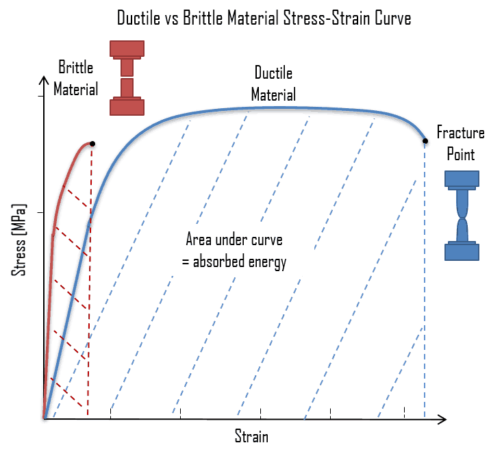
The following figure shows a typical stress-strain curve of a ductile material and a brittle material. A ductile material is a material, where the strength is small, and the plastic region is great. The material will bear more strain (deformation) before fracture. A brittle material is a material where the plastic region is small and the strength of the material is high. The tensile test supplies three descriptive facts about a material. These are the stress at which observable plastic deformation or “yielding” begins; the ultimate tensile strength or maximum intensity of load that can be carried in tension; and the percent elongation or strain (the amount the material will stretch) and the accompanying percent reduction of the cross-sectional area caused by stretching. The rupture or fracture point can also be determined.
References:
Materials Science:
U.S. Department of Energy, Material Science. DOE Fundamentals Handbook, Volume 1 and 2. January 1993.
U.S. Department of Energy, Material Science. DOE Fundamentals Handbook, Volume 2 and 2. January 1993.
William D. Callister, David G. Rethwisch. Materials Science and Engineering: An Introduction 9th Edition, Wiley; 9 edition (December 4, 2013), ISBN-13: 978-1118324578.
Eberhart, Mark (2003). Why Things Break: Understanding the World by the Way It Comes Apart. Harmony. ISBN 978-1-4000-4760-4.
Gaskell, David R. (1995). Introduction to the thermodynamics of Materials (4th ed.). Taylor and Francis Publishing. ISBN 978-1-56032-992-3.
González-Viñas, W. & Mancini, H.L. (2004). An Introduction to Materials Science. Princeton University Press. ISBN 978-0-691-07097-1.
Ashby, Michael; Hugh Shercliff; David Cebon (2007). Materials: engineering, science, processing and design (1st ed.). Butterworth-Heinemann. ISBN 978-0-7506-8391-3.
J. R. Lamarsh, A. J. Baratta, Introduction to Nuclear Engineering, 3d ed., Prentice-Hall, 2001, ISBN: 0-201-82498-1.
See above:
Strength
We hope, this article, Stress-strain Curve – Stress-strain Diagram, helps you. If so, give us a like in the sidebar. Main purpose of this website is to help the public to learn some interesting and important information about materials and their properties.
In this concept, strain is also very important variable, since it defines the deformation of an object. In summary, the mechanical behavior of solids is usually defined by constitutive stress-strain relations. Stress-strain Model
In mechanics of materials, the strength of a material is its ability to withstand an applied load without failure or plastic deformation. Strength of materials basically considers the relationship between the external loads applied to a material and the resulting deformation or change in material dimensions. In designing structures and machines, it is important to consider these factors, in order that the material selected will have adequate strength to resist applied loads or forces and retain its original shape. Strength of a material is its ability to withstand this applied load without failure or plastic deformation.
However, we must note that the load which will deform a small component, will be less than the load to deform a larger component of the same material. Therefore, the load (force) is not a suitable term to describe strength. Instead, we can use the force (load) per unit of area (σ = F/A), called stress, which is constant (until deformation occurs) for a given material regardless of size of the component part. In this concept, strain is also very important variable, since it defines the deformation of an object. In summary, the mechanical behavior of solids is usually defined by constitutive stress-strain relations. A deformation is called elastic deformation, if the stress is a linear function of strain. In other words, stress and strain follows Hooke’s law. Beyond the linear region, stress and strain show nonlinear behavior. This inelastic behavior is called plastic deformation.
Stress
In mechanics and materials science, stress (represented by a lowercase Greek letter sigma – σ) is a physical quantity that expresses the internal forces that neighbouring particles of a continuous material exert on each other, while strain is the measure of the deformation of the material which is not a physical quantity.
Although it is impossible to measure the intensity of this stress, the external load and the area to which it is applied can be measured. Stress (σ) can be equated to the load per unit area or the force (F) applied per cross-sectional area (A) perpendicular to the force as:
When a metal is subjected to a load (force), it is distorted or deformed, no matter how strong the metal or light the load. If the load is small, the distortion will probably disappear when the load is removed. The intensity, or degree, of distortion is known as strain. A deformation is called elastic deformation, if the stress is a linear function of strain. In other words, stress and strain follows Hooke’s law. Beyond the linear region, stress and strain show nonlinear behavior. This inelastic behavior is called plastic deformation.
Stress is the internal resistance, or counterfource, of a material to the distorting effects of an external force or load. These counterforces tend to return the atoms to their normal positions. The total resistance developed is equal to the external load.
Strain
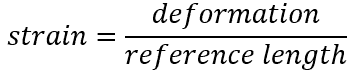
In materials science, strain is also very important variable, since it defines the deformation of an object. Unlike stress in an object, which you can’t actually see, deformation is a visible and measurable quantity. When you pull on a tension rod, you can see the rod physically increase in length (or elongate). When you bend a beam, you see it curve. Deformations are a direct indicator of strain. The mechanical behavior of solids is usually defined by constitutive stress-strain relations. When a metal is subjected to a load (force), it is distorted or deformed, no matter how strong the metal or light the load. If the load is small, the distortion will probably disappear when the load is removed. Such a proportional dimensional change (intensity or degree of the distortion) is called strain and is measured as the total deformation (elongation) per reference length of material due to some applied stress.
Stress – Strain Curve
Strength of materials basically considers the relationship between the external loads applied to a material and the resulting deformation or change in material dimensions. In designing structures and machines, it is important to consider these factors, in order that the material selected will have adequate strength to resist applied loads or forces and retain its original shape. Strength of a material is its ability to withstand this applied load without failure or plastic deformation.
However, we must note that the load which will deform a small component, will be less than the load to deform a larger component of the same material. Therefore, the load (force) is not a suitable term to describe strength. Instead, we can use the force (load) per unit of area (σ = F/A), called stress, which is constant (until deformation occurs) for a given material regardless of size of the component part. In this concept, strain is also very important variable, since it defines the deformation of an object. In summary, the mechanical behavior of solids is usually defined by constitutive stress-strain relations. A deformation is called elastic deformation, if the stress is a linear function of strain. In other words, stress and strain follows Hooke’s law. Beyond the linear region, stress and strain show nonlinear behavior. This inelastic behavior is called plastic deformation.
A schematic diagram for the stress-strain curve of low carbon steel at room temperature is shown in the figure. There are several stages showing different behaviors, which suggests different mechanical properties. To clarify, materials can miss one or more stages shown in the figure, or have totally different stages. In this case we have to distinguish between stress-strain characteristics of ductile and brittle materials. The following points describe the different regions of the stress-strain curve and the importance of several specific locations.
Proportional limit. The proportional limit corresponds to the location of stress at the end of the linear region, so the stress-strain graph is a straight line, and the gradient will be equal to the elastic modulus of the material. For tensile and compressive stress, the slope of the portion of the curve where stress is proportional to strain is referred to as Young’s modulus and Hooke’s Law applies. Between the proportional limit and the yield point the Hooke’s Law becomes questionable between and strain increases more rapidly.
Yield point. The yield point is the point on a stress-strain curve that indicates the limit of elastic behavior and the beginning plastic behavior. Yield strength or yield stress is the material property defined as the stress at which a material begins to deform plastically whereas yield point is the point where nonlinear (elastic + plastic) deformation begins. Prior to the yield point, the material will deform elastically and will return to its original shape when the applied stress is removed. Once the yield point is passed, some fraction of the deformation will be permanent and non-reversible. Some steels and other materials exhibit a behaviour termed a yield point phenomenon. Yield strengths vary from 35 MPa for a low-strength aluminum to greater than 1400 MPa for very high-strength steels.
Ultimate tensile strength. The ultimate tensile strength is the maximum on the engineering stress-strain curve. This corresponds to the maximum stress that can be sustained by a structure in tension. Ultimate tensile strength is often shortened to “tensile strength” or even to “the ultimate.” If this stress is applied and maintained, fracture will result. Often, this value is significantly more than the yield stress (as much as 50 to 60 percent more than the yield for some types of metals). When a ductile material reaches its ultimate strength, it experiences necking where the cross-sectional area reduces locally. The stress-strain curve contains no higher stress than the ultimate strength. Even though deformations can continue to increase, the stress usually decreases after the ultimate strength has been achieved. It is an intensive property; therefore its value does not depend on the size of the test specimen. However, it is dependent on other factors, such as the preparation of the specimen, the presence or otherwise of surface defects, and the temperature of the test environment and material. Ultimate tensile strengths vary from 50 MPa for an aluminum to as high as 3000 MPa for very high-strength steels.
Fracture point: The fracture point is the point of strain where the material physically separates. At this point, the strain reaches its maximum value and the material actually fractures, even though the corresponding stress may be less than the ultimate strength at this point. Ductile materials have a fracture strength lower than the ultimate tensile strength (UTS), whereas in brittle materials the fracture strength is equivalent to the UTS. If a ductile material reaches its ultimate tensile strength in a load-controlled situation, it will continue to deform, with no additional load application, until it ruptures. However, if the loading is displacement-controlled, the deformation of the material may relieve the load, preventing rupture.
In many situations, the yield strength is used to identify the allowable stress to which a material can be subjected. For components that have to withstand high pressures, such as those used in pressurized water reactors (PWRs), this criterion is not adequate. To cover these situations, the maximum shear stress theory of failure has been incorporated into the ASME (The American Society of Mechanical Engineers) Boiler and Pressure Vessel Code, Section III, Rules for Construction of Nuclear Pressure Vessels. This theory states that failure of a piping component occurs when the maximum shear stress exceeds the shear stress at the yield point in a tensile test.
References:
Materials Science:
U.S. Department of Energy, Material Science. DOE Fundamentals Handbook, Volume 1 and 2. January 1993.
U.S. Department of Energy, Material Science. DOE Fundamentals Handbook, Volume 2 and 2. January 1993.
William D. Callister, David G. Rethwisch. Materials Science and Engineering: An Introduction 9th Edition, Wiley; 9 edition (December 4, 2013), ISBN-13: 978-1118324578.
Eberhart, Mark (2003). Why Things Break: Understanding the World by the Way It Comes Apart. Harmony. ISBN 978-1-4000-4760-4.
Gaskell, David R. (1995). Introduction to the thermodynamics of Materials (4th ed.). Taylor and Francis Publishing. ISBN 978-1-56032-992-3.
González-Viñas, W. & Mancini, H.L. (2004). An Introduction to Materials Science. Princeton University Press. ISBN 978-0-691-07097-1.
Ashby, Michael; Hugh Shercliff; David Cebon (2007). Materials: engineering, science, processing and design (1st ed.). Butterworth-Heinemann. ISBN 978-0-7506-8391-3.
J. R. Lamarsh, A. J. Baratta, Introduction to Nuclear Engineering, 3d ed., Prentice-Hall, 2001, ISBN: 0-201-82498-1.
See above:
Strength
We hope, this article, Concept of Stress and Strain – Stress-strain Model, helps you. If so, give us a like in the sidebar. Main purpose of this website is to help the public to learn some interesting and important information about materials and their properties.
In mechanics of materials, the strength of a material is its ability to withstand an applied load without failure or plastic deformation. Strength of materials basically considers the relationship between the external loads applied to a material and the resulting deformation.
In mechanics of materials, the strength of a material is its ability to withstand an applied load without failure or plastic deformation. Strength of materials basically considers the relationship between the external loads applied to a material and the resulting deformation or change in material dimensions. In designing structures and machines, it is important to consider these factors, in order that the material selected will have adequate strength to resist applied loads or forces and retain its original shape. Strength of a material is its ability to withstand this applied load without failure or plastic deformation.
However, we must note that the load which will deform a small component, will be less than the load to deform a larger component of the same material. Therefore, the load (force) is not a suitable term to describe strength. Instead, we can use the force (load) per unit of area (σ = F/A), called stress, which is constant (until deformation occurs) for a given material regardless of size of the component part. In this concept, strain is also very important variable, since it defines the deformation of an object. In summary, the mechanical behavior of solids is usually defined by constitutive stress-strain relations. A deformation is called elastic deformation, if the stress is a linear function of strain. In other words, stress and strain follows Hooke’s law. Beyond the linear region, stress and strain show nonlinear behavior. This inelastic behavior is called plastic deformation.
Stress
In mechanics and materials science, stress (represented by a lowercase Greek letter sigma – σ) is a physical quantity that expresses the internal forces that neighbouring particles of a continuous material exert on each other, while strain is the measure of the deformation of the material which is not a physical quantity.
Although it is impossible to measure the intensity of this stress, the external load and the area to which it is applied can be measured. Stress (σ) can be equated to the load per unit area or the force (F) applied per cross-sectional area (A) perpendicular to the force as:
When a metal is subjected to a load (force), it is distorted or deformed, no matter how strong the metal or light the load. If the load is small, the distortion will probably disappear when the load is removed. The intensity, or degree, of distortion is known as strain. A deformation is called elastic deformation, if the stress is a linear function of strain. In other words, stress and strain follows Hooke’s law. Beyond the linear region, stress and strain show nonlinear behavior. This inelastic behavior is called plastic deformation.
Stress is the internal resistance, or counterfource, of a material to the distorting effects of an external force or load. These counterforces tend to return the atoms to their normal positions. The total resistance developed is equal to the external load.
Types of Stress
Stresses occur in any material that is subject to a load or any applied force. There are many types of stresses, but they can all be generally classified in one of six categories:
Structural stresses are stresses produced in structural members because of the weights they support. The weights provide the loadings. These stresses are found in building foundations and frameworks, as well as in machinery parts.
Residual stresses are stresses caused by manufacturing processes. This type od stress remains in a solid material after the original cause of the stresses has been removed. For example, welding leaves residual stresses in the metals welded. Heat from welding may cause localized expansion, which is taken up during welding by either the molten metal or the placement of parts being welded.
Pressure stresses are stresses induced in vessels containing pressurized materials. The loading is provided by the same force producing the thermodynamics/thermodynamic-properties/what-is-pressure-physics/”>pressure. In a reactor facility, the reactor vessel is a prime example of a pressure vessel. One safety issue that is a long-term problem brought on by the aging of nuclear facilities is pressurized thermal shock (PTS). PTS is the shock experienced by a thick-walled vessel due to the combined stresses from a rapid temperature and/or pressure change.
Thermal stresses exist whenever temperature gradients are present in a material. Different thermodynamics/thermodynamic-properties/what-is-temperature-physics/”>temperatures produce different expansions and subject materials to internal stress. This type of stress is particularly noticeable in mechanisms operating at high temperatures that are cooled by a cold fluid. One safety issue that is a long-term problem brought on by the aging of nuclear facilities is pressurized thermal shock (PTS). PTS is the shock experienced by a thick-walled vessel due to the combined stresses from a rapid temperature and/or pressure change.
Flow stresses occur when a mass of flowing fluid induces a dynamic pressure on a conduit wall. The force of the fluid striking the wall acts as the load. This type of stress may be applied in an unsteady fashion when flow rates fluctuate. Water hammer is an example of a transient flow stress. A Water hammer in pipe or tube is a pressure spike caused by sudden variation of flow rate. and velocity energy is converted to pressure energy.
Fatigue stresses. Fatique is the weakening of a material caused by cyclic loading that results in progressive and localized structural damage and the growth of cracks. Once a crack has initiated, each loading cycle will grow the crack a small amount, The stresses could be due to vibration or thermal cycling.
Applied Stress
From internal point of view, stress intensity within the body of a component is expressed as one of three basic types of internal load, namely, tension, compression, and shear. In engineering practice many loads are torsional rather than pure shear. Mathematically, there are only two types of internal load because tensile and compressive stress may be regarded as the positive and negative versions of the same type of normal loading.
Tensile stress. One of the most common mechanical stress–strain tests is performed in tension. Tensile stress is that type of stress in which the two sections of material on either side of a stress plane tend to pull apart or elongate. The capacity of a material or structure to withstand loads tending to elongate is known as ultimate tensile strength (UTS). Ultimate tensile strength is measured by the maximum stress that a material can withstand while being stretched or pulled before breaking. In the study of strength of materials, tensile strength, compressive strength, and shear strength can be analyzed independently. Because tensile and compressive loads produce stresses that act across a plane, in a direction perpendicular (normal) to the plane, tensile and compressive stresses are called normal stresses.
Compressive stress. Compressive stress is the reverse of tensile stress. Adjacent parts of the material tend to press against each other through a typical stress plane. Compressive stress to bars, columns, etc. leads to shortening. Compressive stress is defined in the same way as the tensile stress but it has negative values so as to express the compression since delta L has the opposite direction. One can increase the compressive stress until compressive strength is reached. Then materials will react with ductile behaviour or with fracture in case of brittle materials. Because tensile and compressive loads produce stresses that act across a plane, in a direction perpendicular (normal) to the plane, tensile and compressive stresses are called normal stresses. The ability of a material to react to compressive stress or pressure is called compressibility.
Shear stress. Shear stress exists when two parts of a material tend to slide across each other in any typical plane of shear upon application of force parallel to that plane. Torsion is a variation of pure shear in which a structural member is twisted. Torsional forces produce a rotational motion about the longitudinal axis of one end of the member relative to the other end. Shear stress is also of great importance in nature, being intimately related to the downslope movement of earth materials (as in case of avalanches).
Strain
In materials science, strain is also very important variable, since it defines the deformation of an object. Unlike stress in an object, which you can’t actually see, deformation is a visible and measurable quantity. When you pull on a tension rod, you can see the rod physically increase in length (or elongate). When you bend a beam, you see it curve. Deformations are a direct indicator of strain. The mechanical behavior of solids is usually defined by constitutive stress-strain relations. When a metal is subjected to a load (force), it is distorted or deformed, no matter how strong the metal or light the load. If the load is small, the distortion will probably disappear when the load is removed. Such a proportional dimensional change (intensity or degree of the distortion) is called strain and is measured as the total deformation (elongation) per reference length of material due to some applied stress.
In mechanics of materials, we can define two basic types of strain:
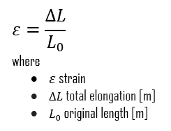
Normal strains. A normal strain results from tensile stress and is a strain computed from relative displacements that are measured perpendicular to two reference planes. Normal strains measure the relative perpendicular movement of one reference plane with respect to another. The symbol for normal strain is usually the lowercase Greek symbol epsilon (ε).
Shear strains. A shear strain results from shear stress and it is a strain computed from relative displacements that are measured parallel to two reference planes. Shear strains measure the relative parallel movement of one reference plane with respect to another. The symbol for shear strain is usually the lowercase Greek symbol gamma (γ ).
Deformation
The deformation is a measure of how much an object deforms from its original dimensions or size in a given direction. Depending on which deformation you measure, you can calculate different types of strain.
A deformation is called elastic deformation, if the stress is a linear function of strain. In other words, stress and strain follows the Hooke’s law. Beyond the linear region, stress and strain show nonlinear behavior. This inelastic behavior is called plastic deformation.
Elastic Deformation. Elastic deformation and elastic strain is a transitory dimensional change that exists only while the initiating stress is applied and disappears immediately upon removal of the stress. When a metal is subjected to a load (force), it is distorted or deformed, no matter how strong the metal or light the load. This deformation may or may not be permanent. Up to a limiting stress, a body will be able to recover its dimensions on removal of the load. The applied stresses cause the atoms in a crystal to move from their equilibrium position. All the atoms are displaced the same amount and still maintain their relative geometry. When the stresses are removed, all the atoms return to their original positions and no permanent deformation occurs.
Plastic Deformation.Plastic deformation and plastic strain is a dimensional change that does not disappear when the initiating stress is removed. It occurs, if the limiting load is exceeded then the body will experience some permanent deformation on removal of the load. Plastic deformation occurs in material bodies after stresses have attained a certain threshold value known as the elastic limit or yield stress, and are the result of slip, or dislocation mechanisms at the atomic level.
Stress – Strain Curve
Strength of materials basically considers the relationship between the external loads applied to a material and the resulting deformation or change in material dimensions. In designing structures and machines, it is important to consider these factors, in order that the material selected will have adequate strength to resist applied loads or forces and retain its original shape. Strength of a material is its ability to withstand this applied load without failure or plastic deformation.
However, we must note that the load which will deform a small component, will be less than the load to deform a larger component of the same material. Therefore, the load (force) is not a suitable term to describe strength. Instead, we can use the force (load) per unit of area (σ = F/A), called stress, which is constant (until deformation occurs) for a given material regardless of size of the component part. In this concept, strain is also very important variable, since it defines the deformation of an object. In summary, the mechanical behavior of solids is usually defined by constitutive stress-strain relations. A deformation is called elastic deformation, if the stress is a linear function of strain. In other words, stress and strain follows Hooke’s law. Beyond the linear region, stress and strain show nonlinear behavior. This inelastic behavior is called plastic deformation.
A schematic diagram for the stress-strain curve of low carbon steel at room temperature is shown in the figure. There are several stages showing different behaviors, which suggests different mechanical properties. To clarify, materials can miss one or more stages shown in the figure, or have totally different stages. In this case we have to distinguish between stress-strain characteristics of ductile and brittle materials. The following points describe the different regions of the stress-strain curve and the importance of several specific locations.
Proportional limit. The proportional limit corresponds to the location of stress at the end of the linear region, so the stress-strain graph is a straight line, and the gradient will be equal to the elastic modulus of the material. For tensile and compressive stress, the slope of the portion of the curve where stress is proportional to strain is referred to as Young’s modulus and Hooke’s Law applies. Between the proportional limit and the yield point the Hooke’s Law becomes questionable between and strain increases more rapidly.
Yield point. The yield point is the point on a stress-strain curve that indicates the limit of elastic behavior and the beginning plastic behavior. Yield strength or yield stress is the material property defined as the stress at which a material begins to deform plastically whereas yield point is the point where nonlinear (elastic + plastic) deformation begins. Prior to the yield point, the material will deform elastically and will return to its original shape when the applied stress is removed. Once the yield point is passed, some fraction of the deformation will be permanent and non-reversible. Some steels and other materials exhibit a behaviour termed a yield point phenomenon. Yield strengths vary from 35 MPa for a low-strength aluminum to greater than 1400 MPa for very high-strength steels.
Ultimate tensile strength. The ultimate tensile strength is the maximum on the engineering stress-strain curve. This corresponds to the maximum stress that can be sustained by a structure in tension. Ultimate tensile strength is often shortened to “tensile strength” or even to “the ultimate.” If this stress is applied and maintained, fracture will result. Often, this value is significantly more than the yield stress (as much as 50 to 60 percent more than the yield for some types of metals). When a ductile material reaches its ultimate strength, it experiences necking where the cross-sectional area reduces locally. The stress-strain curve contains no higher stress than the ultimate strength. Even though deformations can continue to increase, the stress usually decreases after the ultimate strength has been achieved. It is an intensive property; therefore its value does not depend on the size of the test specimen. However, it is dependent on other factors, such as the preparation of the specimen, the presence or otherwise of surface defects, and the temperature of the test environment and material. Ultimate tensile strengths vary from 50 MPa for an aluminum to as high as 3000 MPa for very high-strength steels.
Fracture point: The fracture point is the point of strain where the material physically separates. At this point, the strain reaches its maximum value and the material actually fractures, even though the corresponding stress may be less than the ultimate strength at this point. Ductile materials have a fracture strength lower than the ultimate tensile strength (UTS), whereas in brittle materials the fracture strength is equivalent to the UTS. If a ductile material reaches its ultimate tensile strength in a load-controlled situation, it will continue to deform, with no additional load application, until it ruptures. However, if the loading is displacement-controlled, the deformation of the material may relieve the load, preventing rupture.
In many situations, the yield strength is used to identify the allowable stress to which a material can be subjected. For components that have to withstand high pressures, such as those used in pressurized water reactors (PWRs), this criterion is not adequate. To cover these situations, the maximum shear stress theory of failure has been incorporated into the ASME (The American Society of Mechanical Engineers) Boiler and Pressure Vessel Code, Section III, Rules for Construction of Nuclear Pressure Vessels. This theory states that failure of a piping component occurs when the maximum shear stress exceeds the shear stress at the yield point in a tensile test.
Ductile vs. Brittle – Stress-strain curves
Some materials break very sharply, without plastic deformation, in what is called a brittle failure. Others, which are more ductile, including most metals, experience some plastic deformation and possibly necking before fracture. It is possible to distinguish some common characteristics among the stress–strain curves of various groups of materials. On this basis, it is possible to divide materials into two broad categories; namely:
Ductile Materials. Ductility is the ability of a material to be elongated in tension. Ductile material will deform (elongate) more than brittle material. Ductile materials show large deformation before fracture. In ductile fracture, extensive plastic deformation (necking) takes place before fracture. Ductile fracture (shear fracture) is better than brittle fracture, because there is slow propagation and an absorption of a large amount energy before fracture. Ductility is desirable in the high temperature and high pressure applications in reactor plants because of the added stresses on the metals. High ductility in these applications helps prevent brittle fracture.
Brittle Materials. Brittle materials, when subjected to stress, break with little elastic deformation and without significant plastic deformation. Brittle materials absorb relatively little energy prior to fracture, even those of high strength. In brittle fracture (transgranular cleavage), no apparent plastic deformation takes place before fracture. Cracks propagate rapidly.
The following figure shows a typical stress-strain curve of a ductile material and a brittle material. A ductile material is a material, where the strength is small, and the plastic region is great. The material will bear more strain (deformation) before fracture. A brittle material is a material where the plastic region is small and the strength of the material is high. The tensile test supplies three descriptive facts about a material. These are the stress at which observable plastic deformation or “yielding” begins; the ultimate tensile strength or maximum intensity of load that can be carried in tension; and the percent elongation or strain (the amount the material will stretch) and the accompanying percent reduction of the cross-sectional area caused by stretching. The rupture or fracture point can also be determined.
Strain Hardening
One of stages in the stress-strain curve is the strain hardening region. This region starts as the strain goes beyond yield point, and ends at the ultimate strength point, which is the maximal stress shown in the stress-strain curve. In this region, the stress mainly increases as material elongates, except that there is a nearly flat region at the beginning. Strain hardening is also called work-hardening or cold-working. It is called cold-working because the plastic deformation must occurs at a temperature low enough that atoms cannot rearrange themselves. It is a process of making a metal harder and stronger through plastic deformation. When a metal is plastically deformed, dislocations move and additional dislocations are generated. Dislocations can move if the atoms from one of the surrounding planes break their bonds and rebond with the atoms at the terminating edge. The dislocation density in a metal increases with deformation or cold work because of dislocation multiplication or the formation of new dislocations. The more dislocations within a material, the more they will interact and become pinned or tangled. This will result in a decrease in the mobility of the dislocations and a strengthening of the material.
Hooke’s law
Most polycrystalline materials have within their elastic range an almost constant relationship between stress and strain. In 1678 an English scientist named Robert Hooke ran experiments that provided data that showed that in the elastic range of a material, strain is proportional to stress. Robert Hooke concluded that the force F in any spring is proportional to the extension (the deformation from the relaxed state) x as follows:
F = k · x
where the term k is the stiffness of the spring and x is small compared to the total possible deformation of the spring. It must eventually fail once the forces exceed some limit, since no material can be compressed beyond a certain minimum size, or stretched beyond a maximum size, without some permanent deformation or change of state.
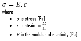
In case of tensional stress of a uniform bar (stress-strain curve), the Hooke’s law describes behaviour of a bar in the elastic region. In this region, the elongation of the bar is directly proportional to the tensile force and the length of the bar and inversely proportional to the cross-sectional area and the modulus of elasticity. Up to a limiting stress, a body will be able to recover its dimensions on removal of the load. The applied stresses cause the atoms in a crystal to move from their equilibrium position. All the atoms are displaced the same amount and still maintain their relative geometry. When the stresses are removed, all the atoms return to their original positions and no permanent deformation occurs. According to the Hooke’s law, the stress is proportional to the strain (in the elastic region), and the slope is Young’s modulus.
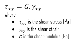
We can extend the same idea of relating stress to strain to shear applications in the linear region, relating shear stress to shear strain to create Hooke’s law for shear stress:
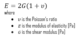
For isotropic materials within the elastic region, you can relate Poisson’s ratio (ν), Young’s modulus of elasticity (E), and the shear modulus of elasticity (G):
The elastic moduli relevant to polycrystalline materials:
Young’s Modulus of Elasticity. The Young’s modulus of elasticity is the elastic modulus for tensile and compressive stress in the linear elasticity regime of a uniaxial deformation and is usually assessed by tensile tests.
Shear Modulus of Elasticity. The shear modulus, or the modulus of rigidity, is derived from the torsion of a cylindrical test piece. It describes the material’s response to shear stress. Its symbol is G. The shear modulus is one of several quantities for measuring the stiffness of materials and it arises in the generalized Hooke’s law.
Bulk Modulus of Elasticity. The bulk modulus of elasticity is describes volumetric elasticity, or the tendency of an object to deform in all directions when uniformly loaded in all directions. For example, it describes the elastic response to hydrostatic pressure and equilateral tension (like the pressure at the bottom of the ocean or a deep swimming pool). It is also the property of a material that determines the elastic response to the application of stress. For a fluid, only the bulk modulus is meaningful.
References:
Materials Science:
U.S. Department of Energy, Material Science. DOE Fundamentals Handbook, Volume 1 and 2. January 1993.
U.S. Department of Energy, Material Science. DOE Fundamentals Handbook, Volume 2 and 2. January 1993.
William D. Callister, David G. Rethwisch. Materials Science and Engineering: An Introduction 9th Edition, Wiley; 9 edition (December 4, 2013), ISBN-13: 978-1118324578.
Eberhart, Mark (2003). Why Things Break: Understanding the World by the Way It Comes Apart. Harmony. ISBN 978-1-4000-4760-4.
Gaskell, David R. (1995). Introduction to the thermodynamics of Materials (4th ed.). Taylor and Francis Publishing. ISBN 978-1-56032-992-3.
González-Viñas, W. & Mancini, H.L. (2004). An Introduction to Materials Science. Princeton University Press. ISBN 978-0-691-07097-1.
Ashby, Michael; Hugh Shercliff; David Cebon (2007). Materials: engineering, science, processing and design (1st ed.). Butterworth-Heinemann. ISBN 978-0-7506-8391-3.
J. R. Lamarsh, A. J. Baratta, Introduction to Nuclear Engineering, 3d ed., Prentice-Hall, 2001, ISBN: 0-201-82498-1.
See above:
Material Properties
We hope, this article, Strength, helps you. If so, give us a like in the sidebar. Main purpose of this website is to help the public to learn some interesting and important information about materials and their properties.
In materials science, ductility is the ability of a material to undergo large plastic deformations prior to failure and it is one of very important characteristics that engineers consider during design.
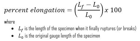
Some materials break very sharply, without plastic deformation, in what is called a brittle failure. Others, which are more ductile, including most metals, experience some plastic deformation and possibly necking before fracture. In materials science, ductility is the ability of a material to undergo large plastic deformations prior to failure and it is one of very important characteristics that engineers consider during design. Ductility may be expressed as percent elongation or percent area reduction from a tensile test. Ductility is an important factor in allowing a structure to survive extreme loads, such as those due large pressure changes, earthquakes and hurricanes, without experiencing a sudden failure or collapse. It is defined as:
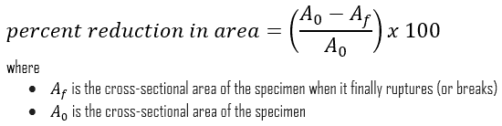
In case of tension test, ductility is measured by a percent reduction in area. It measures the amount of necking (or change in cross-sectional area) that occurs prior to the ultimate failure as follows:
It is possible to distinguish some common characteristics among the stress–strain curves of various groups of materials. On this basis, it is possible to divide materials into two broad categories; namely:
Ductile Materials. Ductility is the ability of a material to be elongated in tension. Ductile material will deform (elongate) more than brittle material. Ductile materials show large deformation before fracture. In ductile fracture, extensive plastic deformation (necking) takes place before fracture. Ductile fracture (shear fracture) is better than brittle fracture, because there is slow propagation and an absorption of a large amount energy before fracture. Ductility is desirable in the high temperature and high pressure applications in reactor plants because of the added stresses on the metals. High ductility in these applications helps prevent brittle fracture.
Brittle Materials. Brittle materials, when subjected to stress, break with little elastic deformation and without significant plastic deformation. Brittle materials absorb relatively little energy prior to fracture, even those of high strength. In brittle fracture (transgranular cleavage), no apparent plastic deformation takes place before fracture. Cracks propagate rapidly.
The distinction between brittleness and ductility isn’t readily apparent, especially because both ductility and brittle behavior are dependent not only on the material in question but also on the nature and type of stress, the rate of loading (fatigue wear) and the thermodynamics/thermodynamic-properties/what-is-temperature-physics/”>temperature (ductile-brittle transition). The following figure shows a typical stress-strain curve of a ductile material and a brittle material. A ductile material is a material, where the strength is small, and the plastic region is great. The material will bear more strain (deformation) before fracture. A brittle material is a material where the plastic region is small and the strength of the material is high. The tensile test supplies three descriptive facts about a material. These are the stress at which observable plastic deformation or “yielding” begins; the ultimate tensile strength or maximum intensity of load that can be carried in tension; and the percent elongation or strain (the amount the material will stretch) and the accompanying percent reduction of the cross-sectional area caused by stretching. The rupture or fracture point can also be determined.
Ductility and Toughness
Ductility is more commonly defined as the ability of a material to deform easily upon the application of a tensile force, or as the ability of a material to withstand plastic deformation without rupture. Ductility may also be thought of in terms of bendability and crushability. Usually, if two materials have the same strength and hardness, the one that has the higher ductility is more desirable. The ductility of many metals can change if conditions are altered. An increase in temperature will increase ductility. A decrease in temperature will cause a decrease in ductility and a change from ductile to brittle behavior. Ductile fracture (shear fracture) is better than brittle fracture, because there is slow propagation and an absorption of a large amount energy before fracture. Ductility is desirable in the high temperature and high pressure applications in reactor plants because of the added stresses on the metals. High ductility in these applications helps prevent brittle fracture. Ductility also contributes to another material property called toughness.Toughness combines strength and ductility in a single measurable property and requires a balance of strength and ductility.
Toughness is the ability of a material to absorb energy and plastically deform without fracturing. One definition of toughness (or more specifically, fracture toughness) is that it is a property that is indicative of a material’s resistance to fracture when a crack (or other stress-concentrating defect) is present. Toughness is typically measured by the Charpy test or the Izod test. The impact test measures toughness under conditions of sudden loading and the presence of flaws such as notches or cracks which will concentrate stress at weak points. Toughness can also be defined with respect to regions of a stress–strain diagram. Toughness is related to the area under the stress–strain curve. The stress-strain curve measures toughness under gradually increasing load. In order to be tough, a material must be both strong and ductile. The following figure shows a typical stress-strain curve of a ductile material and a brittle material. For example, brittle materials (like ceramics) that are strong but with limited ductility are not tough; conversely, very ductile materials with low strengths are also not tough. To be tough, a material should withstand both high stresses and high strains.
Ductile–brittle Transition Temperature
Brittle fracture of the U.S. Liberty Ship Esso Manhattan
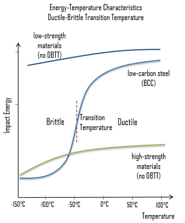
As was written, the distinction between brittleness and ductility isn’t readily apparent, especially because both ductility and brittle behavior are dependent not only on the material in question but also on the temperature (ductile-brittle transition) of the material. The effect of temperature on the nature of the fracture is of considerable importance. Many steels exhibit ductile fracture at elevated temperatures and brittle fracture at low temperatures. The temperature above which a material is ductile and below which it is brittle is known as the ductile–brittle transition temperature (DBTT), nil ductility temperature (NDT), or nil ductility transition temperature. This temperature is not precise, but varies according to prior mechanical and heat treatment and the nature and amounts of impurity elements. It can be determined by some form of drop-weight test (for example, the Charpy or Izod tests).
The ductile–brittle transition temperature (DBTT) is the temperature at which the fracture energy passes below a predetermined value (e.g. 40 J for a standard Charpy impact test). Ductility is an essential requirement for steels used in the construction of reactor components, such as the reactor vessel. Therefore, the DBTT is of significance in the operation of these vessels. In this case, the size of the grain determines the properties of the metal. For example, smaller grain size increases tensile strength, tends to increase ductility and results in a decrease in DBTT. Grain size is controlled by heat treatment in the specifications and manufacturing of reactor vessels. The DBTT can also be lowered by small additions of selected alloying elements such as nickel and manganese to low-carbon steels.
Typically, the low alloy reactor pressure vessel steels are ferritic steels that exhibit the classic ductile-to-brittle transition behaviour with decreasing temperature. This transitional temperature is of the highest importance during plant heatup.
Failure modes:
Low toughness region: Main failure mode is the brittle fracture (transgranular cleavage). In brittle fracture, no apparent plastic deformation takes place before fracture. Cracks propagate rapidly.
High toughness region: Main failure mode is the ductile fracture (shear fracture). In ductile fracture, extensive plastic deformation (necking) takes place before fracture. Ductile fracture is better than brittle fracture, because there is slow propagation and an absorption of a large amount energy before fracture.
In some materials, the transition is sharper than others and typically requires a temperature-sensitive deformation mechanism. For example, in materials with a body-centered cubic (bcc) lattice the DBTT is readily apparent, as the motion of screw dislocations is very temperature sensitive because the rearrangement of the dislocation core prior to slip requires thermal activation. This can be problematic for steels with a high ferrite content. This famously resulted in serious hull cracking in Liberty ships in colder waters during World War II, causing many sinkings. The vessels were constructed of a steel alloy that possessed adequate toughness according to room-temperature tensile tests. The brittle fractures occurred at relatively low ambient temperatures, at about 4°C (40°F), in the vicinity of the transition temperature of the alloy. It must be noted that low-strength FCC metals (e.g. copper alloys) and most HCP metals do not experience a ductile-to-brittle transition and retain tough also for lower temperatures. On the other hand, many high-strength metals (e.g. very high-strength steels) also do not experience a ductile-to-brittle transition, but, in this case, they remain very brittle.
DBTT can also be influenced by external factors such as neutron radiation, which leads to an increase in internal lattice defects and a corresponding decrease in ductility and increase in DBTT.
Irradiation Embrittlement
During the operation of a nuclear power plant, the material of the reactor pressure vessel and the material of other reactor internals are exposed to neutron radiation (especially to fast neutrons >0.5MeV), which results in localized embrittlement of the steel and welds in the area of the reactor core. This phenomenon, known as irradiation embrittlment, results in the steadily increase in DBTT. It is not likely that the DBTT will approach the normal operating temperature of the steel. However, there is a possibility that when the reactor is being shut down or during an abnormal cooldown, the temperature may fall below the DBTT value while the internal pressure is still high. Therefore nuclear regulators require that a reactor vessel material surveillance program be conducted in watercooled power reactors.
Irradiation embrittlement can lead to loss of fracture toughness. Typically, the low alloy reactor pressure vessel steels are ferritic steels that exhibit the classic ductile-to-brittle transition behaviour with decreasing temperature. This transitional temperature is of the highest importance during plant heatup.
Failure modes:
Low toughness region: Main failure mode is the brittle fracture (transgranular cleavage). In brittle fracture, no apparent plastic deformation takes place before fracture. Cracks propagate rapidly.
High toughness region: Main failure mode is the ductile fracture (shear fracture). In ductile fracture, extensive plastic deformation (necking) takes place before fracture. Ductile fracture is better than brittle fracture, because there is slow propagation and an absorption of a large amount energy before fracture.
Neutron irradiation tends to increase the temperature (ductile-to-brittle transition temperature) at which this transition occurs and tends to decrease the ductile toughness.
References:
Materials Science:
U.S. Department of Energy, Material Science. DOE Fundamentals Handbook, Volume 1 and 2. January 1993.
U.S. Department of Energy, Material Science. DOE Fundamentals Handbook, Volume 2 and 2. January 1993.
William D. Callister, David G. Rethwisch. Materials Science and Engineering: An Introduction 9th Edition, Wiley; 9 edition (December 4, 2013), ISBN-13: 978-1118324578.
Eberhart, Mark (2003). Why Things Break: Understanding the World by the Way It Comes Apart. Harmony. ISBN 978-1-4000-4760-4.
Gaskell, David R. (1995). Introduction to the thermodynamics of Materials (4th ed.). Taylor and Francis Publishing. ISBN 978-1-56032-992-3.
González-Viñas, W. & Mancini, H.L. (2004). An Introduction to Materials Science. Princeton University Press. ISBN 978-0-691-07097-1.
Ashby, Michael; Hugh Shercliff; David Cebon (2007). Materials: engineering, science, processing and design (1st ed.). Butterworth-Heinemann. ISBN 978-0-7506-8391-3.
J. R. Lamarsh, A. J. Baratta, Introduction to Nuclear Engineering, 3d ed., Prentice-Hall, 2001, ISBN: 0-201-82498-1.
See above:
Material Properties
We hope, this article, Ductility, helps you. If so, give us a like in the sidebar. Main purpose of this website is to help the public to learn some interesting and important information about materials and their properties.
Material properties are intensive properties, that means they are independent of the amount of mass and may vary from place to place within the system at any moment. The basis of materials science involves studying the structure of materials, and relating them to their properties (mechanical, electrical etc.).
Material properties are intensive properties, that means they are independent of the amount of mass and may vary from place to place within the system at any moment. The basis of materials science involves studying the structure of materials, and relating them to their properties (mechanical, electrical etc.). Once a materials scientist knows about this structure-property correlation, they can then go on to study the relative performance of a material in a given application. The major determinants of the structure of a material and thus of its properties are its constituent chemical elements and the way in which it has been processed into its final form. An understanding of material properties is essential for power plant personnel to understand why a material was selected for certain applications within their facility. Almost all processes that take place in the nuclear facilities involve the use of specialized metals. A basic understanding of material properties is necessary for nuclear facility operators, maintenance personnel, and the technical staff to safely operate and maintain the facility and facility support systems.
Mechanical Properties
Materials are frequently chosen for various applications because they have desirable combinations of mechanical characteristics. For structural applications, material properties are crucial and engineers must take them into account. The mechanical behavior of a material reflects its response or deformation in relation to an applied load or force. Key mechanical design properties are:
Stiffness. Stiffness is the ability of an object to resist deformation in response to an applied force.
Strength. Strength is the ability of a material to resist deformation.
Hardness. Hardness is the ability to withstand surface indentation and scratching.
Ductility. Ductility is the ability of a material to deform under tensile load (% elongation).
Toughness. Toughness is the ability of a material to absorb energy (or withstand shock) and plastically deform without fracturing (or rupturing); a material’s resistance to fracture when stressed; combination of strength and plasticity
Malleability. Malleability is the ability of the material to be flattened into thin sheets under applications of heavy compressive forces without cracking by hot or cold working means.
Creep. Creep is the slow and gradual deformation of an object with respect to time.
References:
Materials Science:
U.S. Department of Energy, Material Science. DOE Fundamentals Handbook, Volume 1 and 2. January 1993.
U.S. Department of Energy, Material Science. DOE Fundamentals Handbook, Volume 2 and 2. January 1993.
William D. Callister, David G. Rethwisch. Materials Science and Engineering: An Introduction 9th Edition, Wiley; 9 edition (December 4, 2013), ISBN-13: 978-1118324578.
Eberhart, Mark (2003). Why Things Break: Understanding the World by the Way It Comes Apart. Harmony. ISBN 978-1-4000-4760-4.
Gaskell, David R. (1995). Introduction to the thermodynamics of Materials (4th ed.). Taylor and Francis Publishing. ISBN 978-1-56032-992-3.
González-Viñas, W. & Mancini, H.L. (2004). An Introduction to Materials Science. Princeton University Press. ISBN 978-0-691-07097-1.
Ashby, Michael; Hugh Shercliff; David Cebon (2007). Materials: engineering, science, processing and design (1st ed.). Butterworth-Heinemann. ISBN 978-0-7506-8391-3.
J. R. Lamarsh, A. J. Baratta, Introduction to Nuclear Engineering, 3d ed., Prentice-Hall, 2001, ISBN: 0-201-82498-1.
See above:
Materials Science
We hope, this article, Material Properties, helps you. If so, give us a like in the sidebar. Main purpose of this website is to help the public to learn some interesting and important information about materials and their properties.
The mechanical behavior of a material reflects its response or deformation in relation to an applied load or force. Mechanical Properties of Materials
Materials are frequently chosen for various applications because they have desirable combinations of mechanical characteristics. For structural applications, material properties are crucial and engineers must take them into account. The mechanical behavior of a material reflects its response or deformation in relation to an applied load or force. Key mechanical design properties are:
Stiffness. Stiffness is the ability of an object to resist deformation in response to an applied force.
Strength. Strength is the ability of a material to resist deformation.
Hardness. Hardness is the ability to withstand surface indentation and scratching.
Ductility. Ductility is the ability of a material to deform under tensile load (% elongation).
Toughness. Toughness is the ability of a material to absorb energy (or withstand shock) and plastically deform without fracturing (or rupturing); a material’s resistance to fracture when stressed; combination of strength and plasticity
Malleability. Malleability is the ability of the material to be flattened into thin sheets under applications of heavy compressive forces without cracking by hot or cold working means.
Creep. Creep is the slow and gradual deformation of an object with respect to time.
References:
Materials Science:
U.S. Department of Energy, Material Science. DOE Fundamentals Handbook, Volume 1 and 2. January 1993.
U.S. Department of Energy, Material Science. DOE Fundamentals Handbook, Volume 2 and 2. January 1993.
William D. Callister, David G. Rethwisch. Materials Science and Engineering: An Introduction 9th Edition, Wiley; 9 edition (December 4, 2013), ISBN-13: 978-1118324578.
Eberhart, Mark (2003). Why Things Break: Understanding the World by the Way It Comes Apart. Harmony. ISBN 978-1-4000-4760-4.
Gaskell, David R. (1995). Introduction to the thermodynamics of Materials (4th ed.). Taylor and Francis Publishing. ISBN 978-1-56032-992-3.
González-Viñas, W. & Mancini, H.L. (2004). An Introduction to Materials Science. Princeton University Press. ISBN 978-0-691-07097-1.
Ashby, Michael; Hugh Shercliff; David Cebon (2007). Materials: engineering, science, processing and design (1st ed.). Butterworth-Heinemann. ISBN 978-0-7506-8391-3.
J. R. Lamarsh, A. J. Baratta, Introduction to Nuclear Engineering, 3d ed., Prentice-Hall, 2001, ISBN: 0-201-82498-1.
See above:
Material Properties
We hope, this article, Mechanical Properties of Materials, helps you. If so, give us a like in the sidebar. Main purpose of this website is to help the public to learn some interesting and important information about materials and their properties.
Twinning is a phenomenon somewhere between a crystallographic defect and a grain boundary. Like a grain boundary, a twin boundary has different crystal orientations on its two sides.
Twinned pyrite crystal
Twinning is a phenomenon somewhere between a crystallographic defect and a grain boundary. Like a grain boundary, a twin boundary has different crystal orientations on its two sides. But unlike a grain boundary, the orientations are not random, but related in a specific, mirror-image way. A twin boundary happens when the crystals on either side of a plane are mirror images of each other.
The boundary between the twinned crystals will be a single plane of atoms. There is no region of disorder and the boundary atoms can be viewed as belonging to the crystal structures of both twins.
There are three modes of formation of twinned crystals. Twins are either grown-in during crystallisation, or the result of mechanical or thermal work. Grown twins are the result of an interruption or change in the lattice during formation or growth due to a possible deformation from a larger substituting ion. Annealing or transformation twins are the result of a change in crystal system during cooling as one form becomes unstable and the crystal structure must re-organize or transform into another more stable form. Deformation or gliding twins are the result of stress on the crystal after the crystal has formed.
References:
Materials Science:
U.S. Department of Energy, Material Science. DOE Fundamentals Handbook, Volume 1 and 2. January 1993.
U.S. Department of Energy, Material Science. DOE Fundamentals Handbook, Volume 2 and 2. January 1993.
William D. Callister, David G. Rethwisch. Materials Science and Engineering: An Introduction 9th Edition, Wiley; 9 edition (December 4, 2013), ISBN-13: 978-1118324578.
Eberhart, Mark (2003). Why Things Break: Understanding the World by the Way It Comes Apart. Harmony. ISBN 978-1-4000-4760-4.
Gaskell, David R. (1995). Introduction to the thermodynamics of Materials (4th ed.). Taylor and Francis Publishing. ISBN 978-1-56032-992-3.
González-Viñas, W. & Mancini, H.L. (2004). An Introduction to Materials Science. Princeton University Press. ISBN 978-0-691-07097-1.
Ashby, Michael; Hugh Shercliff; David Cebon (2007). Materials: engineering, science, processing and design (1st ed.). Butterworth-Heinemann. ISBN 978-0-7506-8391-3.
J. R. Lamarsh, A. J. Baratta, Introduction to Nuclear Engineering, 3d ed., Prentice-Hall, 2001, ISBN: 0-201-82498-1.
See above:
Crystallographic Defects
We hope, this article, Twinning – Twin Boundaries – Crystallographic Defects, helps you. If so, give us a like in the sidebar. Main purpose of this website is to help the public to learn some interesting and important information about materials and their properties.