Facebook Instagram Youtube Twitter

What is Classification of NDT Methods – Definition

The variety of techniques available can also be divided into two groups: surface methods, which are used to identify surface and near surface defects such as cracks and surface porosity, and subsurface methods, that can be used to detect defects that lie under the material’s surface.

Non-destructive testing, NDT, is a very broad group of structural or material inspections and as the name implies, these inspections do not destroy the material/structure being examined. NDT plays a critical role in assuring that structural components and systems perform their function in a reliable and cost effective fashion. Because NDT does not permanently alter the article being inspected, it is a highly valuable technique that can save both money and time in product evaluation, troubleshooting, and research. NDT technicians and engineers define and implement tests that locate and characterize material conditions and flaws that might otherwise cause serious accidents such as, planes to crash, reactors to fail, trains to derail, pipelines to burst, and a variety of troubling events.

This concept is extended, and known as Non-Destructive Evaluation (NDE), when combined with an assessment of the significance of any defects found. However, they are both terms often used interchangeably. Some testing methods must be conducted in a laboratory setting, others may be adapted for use in the field. Several commonly employed NDT techniques and their characteristics are described below.

Classification of NDT Methods

The variety of techniques available can also be divided into two groups: surface methods, which are used to identify surface and near surface defects such as cracks and surface porosity, and subsurface methods, that can be used to detect defects that lie under the material’s surface.

References:

Materials Science:

  1. U.S. Department of Energy, Material Science. DOE Fundamentals Handbook, Volume 1 and 2. January 1993.
  2. U.S. Department of Energy, Material Science. DOE Fundamentals Handbook, Volume 2 and 2. January 1993.
  3. William D. Callister, David G. Rethwisch. Materials Science and Engineering: An Introduction 9th Edition, Wiley; 9 edition (December 4, 2013), ISBN-13: 978-1118324578.
  4. Eberhart, Mark (2003). Why Things Break: Understanding the World by the Way It Comes Apart. Harmony. ISBN 978-1-4000-4760-4.
  5. Gaskell, David R. (1995). Introduction to the Thermodynamics of Materials (4th ed.). Taylor and Francis Publishing. ISBN 978-1-56032-992-3.
  6. González-Viñas, W. & Mancini, H.L. (2004). An Introduction to Materials Science. Princeton University Press. ISBN 978-0-691-07097-1.
  7. Ashby, Michael; Hugh Shercliff; David Cebon (2007). Materials: engineering, science, processing and design (1st ed.). Butterworth-Heinemann. ISBN 978-0-7506-8391-3.
  8. J. R. Lamarsh, A. J. Baratta, Introduction to Nuclear Engineering, 3d ed., Prentice-Hall, 2001, ISBN: 0-201-82498-1.

See above:
NDT

We hope, this article, Classification of NDT Methods, helps you. If so, give us a like in the sidebar. Main purpose of this website is to help the public to learn some interesting and important information about materials and their properties.

What is Material Problems of Turbines – Definition

Material Problems of Turbines.

Material Problems of Turbines

Creep

Creep, known also as cold flow, is the permanent deformation that increases with time under constant load or stress. It results due to long time exposure to large external mechanical stress with in limit of yielding and is more severe in material that are subjected to heat for long time. The rate of deformation is a function of the material’s properties, exposure time, exposure temperature and the applied structural load. Creep is a very important phenomenon if we are using materials at high temperature. Creep is very important in power industry and it is of the highest importance in designing of jet engines. For many relatively short-life creep situations (e.g. turbine blades in military aircraft), time to rupture is the dominant design consideration. Of course, for its determination, creep tests must be conducted to the point of failure; these are termed creep rupture tests.

Erosion Corrosion

Erosion corrosion is the cumulative damage induced by electrochemical corrosion reactions and mechanical effects from relative motion between the electrolyte and the corroding surface. Erosion can also occur in combination with other forms of degradation, such as corrosion. This is referred to as erosion-corrosion. Erosion corrosion is a material degradation process due to the combined effect of corrosion and wear. Nearly all flowing or turbulent corrosive media can cause erosion corrosion. The mechanism can be described as follows:

  • mechanical erosion of the material, or protective (or passive) oxide layer on its surface,
  • enhanced corrosion of the material, if the corrosion rate of the material depends on the thickness of the oxide layer.

Erosion corrosion is found in the systems such as piping, valves, pumps, nozzles, heat exchangers and turbines. Wear is a mechanical material degradation process occurring on rubbing or impacting surfaces, while corrosion involves chemical or electrochemical reactions of the material. Corrosion may accelerate wear and wear may accelerate corrosion.

Steam Oxidation

Steam oxidation behavior is directly linked to implementing ultra-supercritical steam power generation for improved efficiencies and reduced CO2 emissions. Higher temperature means higher efficiency; however, higher corrosion rates occur in a steam atmosphere when ferritic, ferritic‐martensitic, or medium Cr–Ni steels are used.

The materials that were developed over 50–60 years ago are no longer currently suitable for ultra-supercritical regimes due to poor corrosion resistance and inadequate high‐temperature creep and strength properties. These technologies require advanced austenitic steels and nickel (Ni)‐based alloys with superior steam oxidation resistance.

Fatigue

In materials science, fatigue is the weakening of a material caused by cyclic loading that results in progressive, brittle and localized structural damage. Once a crack has initiated, each loading cycle will grow the crack a small amount, even when repeated alternating or cyclic stresses are of an intensity considerably below the normal strength. The stresses could be due to vibration or thermal cycling. Fatigue damage is caused by:

  • simultaneous action of cyclic stress,
  • tensile stress (whether directly applied or residual),
  • plastic strain.

If any one of these three is not present, a fatigue crack will not initiate and propagate. The majority of engineering failures are caused by fatigue.

Although the fracture is of a brittle type, it may take some time to propagate, depending on both the intensity and frequency of the stress cycles. Nevertheless, there is very little, if any, warning before failure if the crack is not noticed. The number of cycles required to cause fatigue failure at a particular peak stress is generally quite large, but it decreases as the stress is increased. For some mild steels, cyclical stresses can be continued indefinitely provided the peak stress (sometimes called fatigue strength) is below the endurance limit value. The type of fatigue of most concern in nuclear power plants is thermal fatigue. Thermal fatigue can arise from thermal stresses produced by cyclic changes in temperature. Large components like the pressurizer, reactor vessel, and reactor system piping are subject to cyclic stresses caused by temperature variations during reactor startup, change in power level, and shutdown.

References:

Materials Science:

  1. U.S. Department of Energy, Material Science. DOE Fundamentals Handbook, Volume 1 and 2. January 1993.
  2. U.S. Department of Energy, Material Science. DOE Fundamentals Handbook, Volume 2 and 2. January 1993.
  3. William D. Callister, David G. Rethwisch. Materials Science and Engineering: An Introduction 9th Edition, Wiley; 9 edition (December 4, 2013), ISBN-13: 978-1118324578.
  4. Eberhart, Mark (2003). Why Things Break: Understanding the World by the Way It Comes Apart. Harmony. ISBN 978-1-4000-4760-4.
  5. Gaskell, David R. (1995). Introduction to the Thermodynamics of Materials (4th ed.). Taylor and Francis Publishing. ISBN 978-1-56032-992-3.
  6. González-Viñas, W. & Mancini, H.L. (2004). An Introduction to Materials Science. Princeton University Press. ISBN 978-0-691-07097-1.
  7. Ashby, Michael; Hugh Shercliff; David Cebon (2007). Materials: engineering, science, processing and design (1st ed.). Butterworth-Heinemann. ISBN 978-0-7506-8391-3.
  8. J. R. Lamarsh, A. J. Baratta, Introduction to Nuclear Engineering, 3d ed., Prentice-Hall, 2001, ISBN: 0-201-82498-1.

See above:
Material Problems

We hope, this article, Material Problems of Turbines, helps you. If so, give us a like in the sidebar. Main purpose of this website is to help the public to learn some interesting and important information about materials and their properties.

What are Fuel Failure Mechanisms – Definition

There are various fuel failure root causes, that have been identified in past. In the early dates of PWR and BWR operations, these causes were predominantly fabrication defects or fretting.

There are various fuel failure root causes, that have been identified in past. In the early dates of PWR and BWR operations, these causes were predominantly fabrication defects or fretting. The following list is not complete, there are also failure mechanisms that are typical for certain reactor and fuel design. It must be also noted that many of fuel failure causes were never identified and remain unknown.

  • Fretting. Fretting was one of main failure mechanisms in the early dates of PWR and BWR operations. It has typically two variants.
    • Debris fretting. Debris fretting can be caused by any debris (foregn material – usually metallic) that can enter the fuel bundle and that has the potential of becoming lodged between the spacer grid and a fuel rod. Fretting wear of fuel cladding can results in cladding penetration.
    • Grid-to-rod fretting. Grid-to-rod fretting arises from vibration of the fuel element generated by the high coolant
      velocity through the spacing grid. Spacing grids are welded onto the guide tubes and ensure, by means of springs and dimples, fuel rod support, and spacing. High coolant velocity can cause the rod to rub against the part of the spacer grid
      that holds it. This type of cladding wear can be minimized by proper design of the spacing grid. Baffle-jetting is usually grouped under grid-to-rod fretting.
  • Pellet-cladding interaction (PCI). Failures due to PCI are typical for power changes, rod movement and plant startup. They usually occur within a few hours or days following a power ramp or control rods movement. This results especially in startup ramp rate restrictions.
  • Dryout. In BWRs, when the heat flux exceeds a critical value (CHF – critical heat flux) the flow pattern may reach the dryout conditions (thin film of liquid disappears). The heat transfer from the fuel surface into the coolant is deteriorated, with the result of a drastically increased fuel surface temperature. This phenomenon can cause failure of affected fuel rod.
  • Fabrication defects
    • End-plug weld defects.
    • Cladding creep collapse. Cladding collapse can be caused by densification of the fuel pellets forming axial gaps in the pellet column resulted in collapse from outer pressure. Since creep is time dependent, full collapse typically occur at higher burnup. This type of failure can be eliminated through the use of pellets with moderate densification and pre-pressurization of rods.
    • Missing pellet surface
  • Internal Hydriding. Inadvertent inclusion of hydrogen-containing materials inside a fuel rod can result in hydriding and thus embrittlement of fuel cladding. Hydrogen sources were mainly residual moisture or organic contamination in fuel pellets/rods. This cause of failure has been practically eliminated through improved manufacturing.
  • Crud induced corrosion.  Crud induced corrosion failures are either due to abnormally high heat flux exceeding heat flux or burnup corrosion limits or to water chemistry problems leading to excessive crud deposits. In BWRs, crud induced corrosion was one of the major causes of fuel failure in the 1980s.
  • Delayed hydride cracking (DHC). Delayed hydride cracking is time-dependent crack initiation and propagation through fracture of hydrides that can form ahead of the crack tip. This type of failure can be initiated by long cracks at the outer surface of the cladding, which can propagate in an axial/radial direction. This failure mechanism may potentially limit high burnup
    operation.
  • Fuel handling damages

See also: IAEA, Review of fuel failures in water cooled reactors. No. NF-T-2.1. ISBN 978–92–0–102610–1, Vienna, 2010.

Loss of Tightness of Fuel Cladding

Cladding prevents radioactive fission products from escaping the fuel matrix into the reactor coolant and contaminating it. Emergence of a leak in that cladding results in:

  • the transport of specific chemical elements (fission products) that are stable, and radioactive (iodinexenonkrypton…) into the reactor’s primary circuit
  • deposits of long-lived isotopes (cesiumstrontiumtechnetium…), or even, in exceptional circumstances, of alpha emitters onto the piping of the primary circuit, or of ancillary circuits
  • an increase in the overall level of irradiation for that circuit, from the level already due to activation products (corrosion products, e.g. cobalt, chromium, iron in particular)

A leak thus poses a major challenge in operational terms, for a power plant operator, since it has a direct bearing on the level of radiological exposure workers are subjected to, when running the plant, or carrying out maintenance. Although fuel failures have rarely been a safety related issue, their impact on plant operational costs due to:

  • premature fuel discharge,
  • following cycle shortening,
  • possible unscheduled outages,
  • increased spent fuel volume

One of the necessary steps to reach the zero defect goal is to understand the root causes of the failures and their mechanisms, so that some corrective actions can be implemented, either through improvements in fuel design and fabrication by fuel suppliers, or operational changes, such as reduced power maneuvering.

Special Reference: CEA, Nuclear Energy Division. Nuclear Fuels, ISBN 978-2-281-11345-7

References:

Materials Science:

  1. U.S. Department of Energy, Material Science. DOE Fundamentals Handbook, Volume 1 and 2. January 1993.
  2. U.S. Department of Energy, Material Science. DOE Fundamentals Handbook, Volume 2 and 2. January 1993.
  3. William D. Callister, David G. Rethwisch. Materials Science and Engineering: An Introduction 9th Edition, Wiley; 9 edition (December 4, 2013), ISBN-13: 978-1118324578.
  4. Eberhart, Mark (2003). Why Things Break: Understanding the World by the Way It Comes Apart. Harmony. ISBN 978-1-4000-4760-4.
  5. Gaskell, David R. (1995). Introduction to the Thermodynamics of Materials (4th ed.). Taylor and Francis Publishing. ISBN 978-1-56032-992-3.
  6. González-Viñas, W. & Mancini, H.L. (2004). An Introduction to Materials Science. Princeton University Press. ISBN 978-0-691-07097-1.
  7. Ashby, Michael; Hugh Shercliff; David Cebon (2007). Materials: engineering, science, processing and design (1st ed.). Butterworth-Heinemann. ISBN 978-0-7506-8391-3.
  8. J. R. Lamarsh, A. J. Baratta, Introduction to Nuclear Engineering, 3d ed., Prentice-Hall, 2001, ISBN: 0-201-82498-1.

See above:
Material Problems

We hope, this article, Fuel Failure Mechanisms, helps you. If so, give us a like in the sidebar. Main purpose of this website is to help the public to learn some interesting and important information about materials and their properties.

What is In-vessel Retention – Definition

The in-vessel retention can be achieved by full flooding of reactor cavity to cool the external wall of the lower head thereby avoiding structural failure by creep rupture.

With regards to the safety of the Nuclear Power Plants (NPP) in case of a severe nuclear accident, one of the main challenges associated is the retention of the molten nuclear fuel and reactor internals, called corium, within the Reactor Pressure Vessel (RPV). One of the ways of cooling corium with in the RPV is by cooling the vessel from outside. The in-vessel retention can be achieved by full flooding of reactor cavity to cool the external wall of the lower head thereby avoiding structural failure by creep rupture. This strategy is termed as In-Vessel Retention (IVR). In case of the In-Vessel Retention (IVR) strategy, it is expected that the corium pool will be surrounded by an oxide crust, which will be in contact with molten steel from top of the pool as well as from sides of the vessel. Application of this approach to large power reactors is not trivial because of relatively short time between the detection of core melting and the lower head failure.

References:

Materials Science:

  1. U.S. Department of Energy, Material Science. DOE Fundamentals Handbook, Volume 1 and 2. January 1993.
  2. U.S. Department of Energy, Material Science. DOE Fundamentals Handbook, Volume 2 and 2. January 1993.
  3. William D. Callister, David G. Rethwisch. Materials Science and Engineering: An Introduction 9th Edition, Wiley; 9 edition (December 4, 2013), ISBN-13: 978-1118324578.
  4. Eberhart, Mark (2003). Why Things Break: Understanding the World by the Way It Comes Apart. Harmony. ISBN 978-1-4000-4760-4.
  5. Gaskell, David R. (1995). Introduction to the Thermodynamics of Materials (4th ed.). Taylor and Francis Publishing. ISBN 978-1-56032-992-3.
  6. González-Viñas, W. & Mancini, H.L. (2004). An Introduction to Materials Science. Princeton University Press. ISBN 978-0-691-07097-1.
  7. Ashby, Michael; Hugh Shercliff; David Cebon (2007). Materials: engineering, science, processing and design (1st ed.). Butterworth-Heinemann. ISBN 978-0-7506-8391-3.
  8. J. R. Lamarsh, A. J. Baratta, Introduction to Nuclear Engineering, 3d ed., Prentice-Hall, 2001, ISBN: 0-201-82498-1.

See above:
Material Problems

We hope, this article, In-vessel Retention, helps you. If so, give us a like in the sidebar. Main purpose of this website is to help the public to learn some interesting and important information about materials and their properties.

What are Materials for Steam Turbines – Definition

The range of alloys used in steam turbines is relatively small, partly because of the need to ensure a good match of thermal properties, such as expansion and conductivity, and partly because of the need for high-temperature strength at acceptable cost.
Superalloys
Steam Turbine Blade. Superalloys (typically face-centered cubic austenitic alloys) based on Co, Ni, and Fe are capable of being engineered to be highly resistant to creep, and have thus arisen as an ideal material in high-temperature environments. Source wikipedia.org License: CC BY-SA 3.0

Most of nuclear power plants operates a single-shaft turbine-generator that consists of one multi-stage HP turbine and three parallel multi-stage LP turbines, a main generator and an exciter.  HP Turbine is usually double-flow reaction turbine with about 10 stages with shrouded blades and produces about 30-40% of the gross power output of the power plant unit. LP turbines are usually double-flow reaction turbines with about 5-8 stages (with shrouded blades and with free-standing blades of last 3 stages). LP turbines produce approximately 60-70% of the gross power output of the power plant unit. Each turbine rotor is mounted on two bearings, i.e. there are double bearings between each turbine module. The range of alloys used in steam turbines is relatively small, partly because of the need to ensure a good match of thermal properties, such as expansion and conductivity, and partly because of the need for high-temperature strength at acceptable cost.

  • Material for turbine rotors. They rotors of steam turbines are usually made of low-alloy steel. The role of the alloying elements is to increase hardenability in order to optimize mechanical properties and toughness after heat treatment. The rotors or are required to handle the highest steam conditions therefore the alloy most commonly used is CrMoV steel.
  • Material for casing. The casings of steam turbines typically are large structures with complex shapes that must provide the pressure containment for the steam turbine. Because of the size of these components, their cost has a strong impact on the overall cost of the turbine.The materials used currently for inner and outer casings are usually low-alloy CrMo steels (e.g. the 1-2CrMo steel). For higher temperatures, cast 9CrMoVNb alloys are considered to be adequate in terms of strength.
  • Material of turbine blading. For gas turbines, the turbine blades are often the limiting component.  The highest temperature in the cycle occurs at the end of the combustion process, and it is limited by the maximum temperature that the turbine blades can withstand. As usual, metallurgical considerations (about 1700 K) place an upper limits on thermal efficiency. Therefore turbine blades often use exotic materials like superalloys and many different methods of cooling, such as internal air channels, boundary layer cooling, and thermal barrier coatings. The development of superalloys in the 1940s and new processing methods such as vacuum induction melting in the 1950s greatly increased the temperature capability of turbine blades. Modern turbine blades often use nickel-based superalloys that incorporate chromium, cobalt, and rhenium.
  • Steam turbine blades are not exposed to such high temperatures, but they must withstand an operation with two-phase fluid. High content of water droplets can cause the rapid impingement and erosion of the blades which occurs when condensed water is blasted onto the blades. To prevent this, for example, condensate drains are installed in the steam piping leading to the turbine. Another challenge for engineers is the design of blades of the last stage of LP turbine. These blades must be (due to high specific volume of steam) very long, which induces enormous centrifugal forces during operation. Therefore, turbine blades are subjected to stress from centrifugal force (turbine stages can rotate at tens of thousands of revolutions per minute (RPM), but usually at 1800 RPM) and fluid forces that can cause fracture, yielding, or creep failures.

Material Problems of Turbines

Creep

Creep, known also as cold flow, is the permanent deformation that increases with time under constant load or stress. It results due to long time exposure to large external mechanical stress with in limit of yielding and is more severe in material that are subjected to heat for long time. The rate of deformation is a function of the material’s properties, exposure time, exposure temperature and the applied structural load. Creep is a very important phenomenon if we are using materials at high temperature. Creep is very important in power industry and it is of the highest importance in designing of jet engines. For many relatively short-life creep situations (e.g. turbine blades in military aircraft), time to rupture is the dominant design consideration. Of course, for its determination, creep tests must be conducted to the point of failure; these are termed creep rupture tests.

Erosion Corrosion

Erosion corrosion is the cumulative damage induced by electrochemical corrosion reactions and mechanical effects from relative motion between the electrolyte and the corroding surface. Erosion can also occur in combination with other forms of degradation, such as corrosion. This is referred to as erosion-corrosion. Erosion corrosion is a material degradation process due to the combined effect of corrosion and wear. Nearly all flowing or turbulent corrosive media can cause erosion corrosion. The mechanism can be described as follows:

  • mechanical erosion of the material, or protective (or passive) oxide layer on its surface,
  • enhanced corrosion of the material, if the corrosion rate of the material depends on the thickness of the oxide layer.

Erosion corrosion is found in the systems such as piping, valves, pumps, nozzles, heat exchangers and turbines. Wear is a mechanical material degradation process occurring on rubbing or impacting surfaces, while corrosion involves chemical or electrochemical reactions of the material. Corrosion may accelerate wear and wear may accelerate corrosion.

Steam Oxidation

Steam oxidation behavior is directly linked to implementing ultra-supercritical steam power generation for improved efficiencies and reduced CO2 emissions. Higher temperature means higher efficiency; however, higher corrosion rates occur in a steam atmosphere when ferritic, ferritic‐martensitic, or medium Cr–Ni steels are used.

The materials that were developed over 50–60 years ago are no longer currently suitable for ultra-supercritical regimes due to poor corrosion resistance and inadequate high‐temperature creep and strength properties. These technologies require advanced austenitic steels and nickel (Ni)‐based alloys with superior steam oxidation resistance.

Fatigue

In materials science, fatigue is the weakening of a material caused by cyclic loading that results in progressive, brittle and localized structural damage. Once a crack has initiated, each loading cycle will grow the crack a small amount, even when repeated alternating or cyclic stresses are of an intensity considerably below the normal strength. The stresses could be due to vibration or thermal cycling. Fatigue damage is caused by:

  • simultaneous action of cyclic stress,
  • tensile stress (whether directly applied or residual),
  • plastic strain.

If any one of these three is not present, a fatigue crack will not initiate and propagate. The majority of engineering failures are caused by fatigue.

Although the fracture is of a brittle type, it may take some time to propagate, depending on both the intensity and frequency of the stress cycles. Nevertheless, there is very little, if any, warning before failure if the crack is not noticed. The number of cycles required to cause fatigue failure at a particular peak stress is generally quite large, but it decreases as the stress is increased. For some mild steels, cyclical stresses can be continued indefinitely provided the peak stress (sometimes called fatigue strength) is below the endurance limit value. The type of fatigue of most concern in nuclear power plants is thermal fatigue. Thermal fatigue can arise from thermal stresses produced by cyclic changes in temperature. Large components like the pressurizer, reactor vessel, and reactor system piping are subject to cyclic stresses caused by temperature variations during reactor startup, change in power level, and shutdown.

References:

Materials Science:

  1. U.S. Department of Energy, Material Science. DOE Fundamentals Handbook, Volume 1 and 2. January 1993.
  2. U.S. Department of Energy, Material Science. DOE Fundamentals Handbook, Volume 2 and 2. January 1993.
  3. William D. Callister, David G. Rethwisch. Materials Science and Engineering: An Introduction 9th Edition, Wiley; 9 edition (December 4, 2013), ISBN-13: 978-1118324578.
  4. Eberhart, Mark (2003). Why Things Break: Understanding the World by the Way It Comes Apart. Harmony. ISBN 978-1-4000-4760-4.
  5. Gaskell, David R. (1995). Introduction to the Thermodynamics of Materials (4th ed.). Taylor and Francis Publishing. ISBN 978-1-56032-992-3.
  6. González-Viñas, W. & Mancini, H.L. (2004). An Introduction to Materials Science. Princeton University Press. ISBN 978-0-691-07097-1.
  7. Ashby, Michael; Hugh Shercliff; David Cebon (2007). Materials: engineering, science, processing and design (1st ed.). Butterworth-Heinemann. ISBN 978-0-7506-8391-3.
  8. J. R. Lamarsh, A. J. Baratta, Introduction to Nuclear Engineering, 3d ed., Prentice-Hall, 2001, ISBN: 0-201-82498-1.

See above:
Material Problems

We hope, this article, Materials for Steam Turbines, helps you. If so, give us a like in the sidebar. Main purpose of this website is to help the public to learn some interesting and important information about materials and their properties.

What is Nuclear Meltdown – Definition

The core melt accident is a severe nuclear reactor accident that results in core damage from overheating. This type of accident is known under term a nuclear meltdown (core meltdown), but this is not officially defined.

Reactor core melt accident is an event or sequence of events that result in the melting of part of the fuel in the reactor core. Although this event is very unlikely, it cannot be ruled out. There are many and many barriers that have to be breached. Especially, common (usually 3×100%) failure of the Emergency Core Cooling System (ECCS) must occur after severe loss of coolant accident.

This type of accident is known under term a nuclear meltdown (core meltdown), but this is not officially defined by the International Atomic Energy Agency or by the Nuclear Regulatory Commission. The core melt accident is a severe nuclear reactor accident that results in core damage from overheating. It occurs when the heat generated by a nuclear reactor exceeds the heat removed by the cooling systems to the point where at least one nuclear fuel element exceeds its melting point. The heat causing the melting of a reactor may originate from the nuclear chain reaction, but more commonly decay heat of the fission products contained in the fuel rods is the primary heat source.

If the reactor core remains dry for a considerable length of time, the temperature of the fuel rods rises and may locally reach levels that cause significant and irreversible core degradation. The mechanisms of this degradation are both chemical and mechani­cal. Depending on the local temperature levels, degradation may result in more or less severe hydrogen production, fission product (FP) release, and molten corium formation and propagation towards the lower head.

Special reference: Nuclear Power Reactor Core Melt Accidents ISBN: 978-2-7598-1835-8, IRSN 2015.

Nuclear Fuel Melting

The thermal conductivity of uranium dioxide is very low when compared with metal uranium, uranium nitride, uranium carbide and zirconium cladding material. The thermal conductivity is one of parameters, which determine the fuel centerline temperature. This low thermal conductivity can result in localised overheating in the fuel centerline and therefore this overheating must be avoided.  Overheating of the fuel is prevented by maintaining the steady state peak linear heat rate (LHR) or the Heat Flux Hot Channel Factor – FQ(z) below the level at which fuel centerline melting occurs. Expansion of the fuel pellet upon centerline melting may cause the pellet to stress the cladding to the point of failure.

Although the melting point of UO2 is over 2,800°C,fuel is usually operated at a much lower peak centerline temperatures (less than 1,400°C). This provides enough margin to fuel melting and to loss of fuel integrity. In general, fuel melting must be excluded for condition III and condition IV accidents as well. But the Fukushima Daiichi nuclear disaster in 2011 raises the safety problem of nuclear power plants to a new level in the world. It is difficult to predict these events and all other beyond design-basis accidents and prepare for them due to their extreme rarity. Under these infrequent circumstances the plant may be unable to operate safely. Reduction in the safety margin of a plant can cause a catastrophic failures such as meltdowns

In case of nuclear fuel melting, it is necessary to distinguish in which event the fuel melting temperature is reached. Fuel melting can occur:

  • Slow fuel rod overpower. In the event of an increase in fuel overpower that is slow compared to the rate of heat transfer through the fuel, melting occurs only on a local scale.
  • Loss of ultimate heat sink. In the event of loss of reactor coolant, the power of the rod decreases, the fuel temperature is only a few tens of degrees Celsius higher than the cladding temperature.
  • RIA accidents. In these accidents, the large and rapid deposition of energy in the fuel can result in melting, fragmentation, and dispersal of fuel.
References:

Materials Science:

  1. U.S. Department of Energy, Material Science. DOE Fundamentals Handbook, Volume 1 and 2. January 1993.
  2. U.S. Department of Energy, Material Science. DOE Fundamentals Handbook, Volume 2 and 2. January 1993.
  3. William D. Callister, David G. Rethwisch. Materials Science and Engineering: An Introduction 9th Edition, Wiley; 9 edition (December 4, 2013), ISBN-13: 978-1118324578.
  4. Eberhart, Mark (2003). Why Things Break: Understanding the World by the Way It Comes Apart. Harmony. ISBN 978-1-4000-4760-4.
  5. Gaskell, David R. (1995). Introduction to the Thermodynamics of Materials (4th ed.). Taylor and Francis Publishing. ISBN 978-1-56032-992-3.
  6. González-Viñas, W. & Mancini, H.L. (2004). An Introduction to Materials Science. Princeton University Press. ISBN 978-0-691-07097-1.
  7. Ashby, Michael; Hugh Shercliff; David Cebon (2007). Materials: engineering, science, processing and design (1st ed.). Butterworth-Heinemann. ISBN 978-0-7506-8391-3.
  8. J. R. Lamarsh, A. J. Baratta, Introduction to Nuclear Engineering, 3d ed., Prentice-Hall, 2001, ISBN: 0-201-82498-1.

See above:
Material Problems

We hope, this article, Nuclear Meltdown, helps you. If so, give us a like in the sidebar. Main purpose of this website is to help the public to learn some interesting and important information about materials and their properties.

What is Corium – Definition

Corium, also called fuel-containing material (FCM), is a lava-like material created in the core of a nuclear reactor during a meltdown accident.

Corium, also called fuel-containing material (FCM), is a lava-like material created in the core of a nuclear reactor during a meltdown accident. It consists of:

  • mixture of nuclear fuel and oxidized zirconium clad,
  • fission products,
  • control rods,
  • structural materials from the affected parts of the reactor, products of their chemical reaction with air, water and steam,
  • and, in the event that the reactor vessel is breached, molten concrete from the floor of the reactor room.

If the temperature reaches the melting point of UO2, a fuel degrades usually from the center of the core. Due to the formation of the eutectic liquids, the melting temperature may be several hundred degrees below that of the UO2 melting point (3100 K). Zirconium from fuel clad, together with other metals, reacts with water and produces zirconium dioxide and hydrogen. The production of hydrogen is a major danger in reactor accidents. As the eutectic molten mass increases, the corium pool may be formed and expands axially and radially in the core until it reaches either the baffle or the core support plate. At this moment, the corium flows into the lower head. The degradation may ultimately result in very different configurations in the core simultaneously, ranging from intact or barely degraded rods to the formation of a corium pool or a bed of debris.

In all cases, the corium gradually evaporates the water present in the lower head. If there is no additional water supply and the debris con­figuration is such that it cannot be cooled effectively, the materials’ temperature gra­dually rises until it reaches the melting point of the steel structures (plates, tubes, etc.) located in the lower head. In the case of adequate cooling of the corium, it can solidify and the damage is limited to the reactor itself. However, in the absence of adequate cooling, corium may melt through the reactor vessel and flow out or be ejected as a molten stream by the pressure inside the reactor vessel.

However, core reflooding may not be beneficial in all conditions. The following pheomena can occur during reflooding:

  • massive steam generation, with hydrogen production and an increase in reactor
  • coolant system pressure;
  • steam explosion through corium-water interaction;
  • continuation of core melt, despite water inflow;
  • faster release of fission products.

In the event of reactor-vessel failure during a core melt accident, the corium resulting from this core melt and the melting of internal structures will pour onto the reactor pit basemat. The molten core-concrete interaction (MCCI) is treated as one of the important phenomena that may lead to the late containment failure by basemat penetration in a hypothetical severe accident of light water reactors (LWRs). The process is driven by the high initial temperature of the molten corium and the decay heat that is generated inside the melt by the radioactive decay of the fission products. Obviously, the progression of MCCI takes paramount importance and plays a key role to threaten the integrity of the containment, the last barrier of fission products.

In-vessel Retention

With regards to the safety of the Nuclear Power Plants (NPP) in case of a severe nuclear accident, one of the main challenges associated is the retention of the molten nuclear fuel and reactor internals, called corium, within the Reactor Pressure Vessel (RPV). One of the ways of cooling corium with in the RPV is by cooling the vessel from outside. The in-vessel retention can be achieved by full flooding of reactor cavity to cool the external wall of the lower head thereby avoiding structural failure by creep rupture. This strategy is termed as In-Vessel Retention (IVR). In case of the In-Vessel Retention (IVR) strategy, it is expected that the corium pool will be surrounded by an oxide crust, which will be in contact with molten steel from top of the pool as well as from sides of the vessel. Application of this approach to large power reactors is not trivial because of relatively short time between the detection of core melting and the lower head failure.

References:

Materials Science:

  1. U.S. Department of Energy, Material Science. DOE Fundamentals Handbook, Volume 1 and 2. January 1993.
  2. U.S. Department of Energy, Material Science. DOE Fundamentals Handbook, Volume 2 and 2. January 1993.
  3. William D. Callister, David G. Rethwisch. Materials Science and Engineering: An Introduction 9th Edition, Wiley; 9 edition (December 4, 2013), ISBN-13: 978-1118324578.
  4. Eberhart, Mark (2003). Why Things Break: Understanding the World by the Way It Comes Apart. Harmony. ISBN 978-1-4000-4760-4.
  5. Gaskell, David R. (1995). Introduction to the Thermodynamics of Materials (4th ed.). Taylor and Francis Publishing. ISBN 978-1-56032-992-3.
  6. González-Viñas, W. & Mancini, H.L. (2004). An Introduction to Materials Science. Princeton University Press. ISBN 978-0-691-07097-1.
  7. Ashby, Michael; Hugh Shercliff; David Cebon (2007). Materials: engineering, science, processing and design (1st ed.). Butterworth-Heinemann. ISBN 978-0-7506-8391-3.
  8. J. R. Lamarsh, A. J. Baratta, Introduction to Nuclear Engineering, 3d ed., Prentice-Hall, 2001, ISBN: 0-201-82498-1.

See above:
Material Problems

We hope, this article, Corium, helps you. If so, give us a like in the sidebar. Main purpose of this website is to help the public to learn some interesting and important information about materials and their properties.

What is Nuclear Fuel Melting – Definition

Although the melting point of UO2 is over 2,800°C,fuel is usually operated at a much lower peak centerline temperatures (less than 1,400°C). This provides enough margin to fuel melting and to loss of fuel integrity. In general, fuel melting must be excluded for condition III and condition IV accidents as well. Nuclear Fuel Melting

The thermal conductivity of uranium dioxide is very low when compared with metal uranium, uranium nitride, uranium carbide and zirconium cladding material. The thermal conductivity is one of parameters, which determine the fuel centerline temperature. This low thermal conductivity can result in localised overheating in the fuel centerline and therefore this overheating must be avoided.  Overheating of the fuel is prevented by maintaining the steady state peak linear heat rate (LHR) or the Heat Flux Hot Channel Factor – FQ(z) below the level at which fuel centerline melting occurs. Expansion of the fuel pellet upon centerline melting may cause the pellet to stress the cladding to the point of failure.

Although the melting point of UO2 is over 2,800°C,fuel is usually operated at a much lower peak centerline temperatures (less than 1,400°C). This provides enough margin to fuel melting and to loss of fuel integrity. In general, fuel melting must be excluded for condition III and condition IV accidents as well. But the Fukushima Daiichi nuclear disaster in 2011 raises the safety problem of nuclear power plants to a new level in the world. It is difficult to predict these events and all other beyond design-basis accidents and prepare for them due to their extreme rarity. Under these infrequent circumstances the plant may be unable to operate safely. Reduction in the safety margin of a plant can cause a catastrophic failures such as meltdowns

In case of nuclear fuel melting, it is necessary to distinguish in which event the fuel melting temperature is reached. Fuel melting can occur:

  • Slow fuel rod overpower. In the event of an increase in fuel overpower that is slow compared to the rate of heat transfer through the fuel, melting occurs only on a local scale.
  • Loss of ultimate heat sink. In the event of loss of reactor coolant, the power of the rod decreases, the fuel temperature is only a few tens of degrees Celsius higher than the cladding temperature.
  • RIA accidents. In these accidents, the large and rapid deposition of energy in the fuel can result in melting, fragmentation, and dispersal of fuel.

Reactor Core Melt Accident

Reactor core melt accident is an event or sequence of events that result in the melting of part of the fuel in the reactor core. Although this event is very unlikely, it cannot be ruled out. There are many and many barriers that have to be breached. Especially, common (usually 3×100%) failure of the Emergency Core Cooling System (ECCS) must occur after severe loss of coolant accident.

This type of accident is known under term a nuclear meltdown (core meltdown), but this is not officially defined by the International Atomic Energy Agency or by the Nuclear Regulatory Commission. The core melt accident is a severe nuclear reactor accident that results in core damage from overheating. It occurs when the heat generated by a nuclear reactor exceeds the heat removed by the cooling systems to the point where at least one nuclear fuel element exceeds its melting point. The heat causing the melting of a reactor may originate from the nuclear chain reaction, but more commonly decay heat of the fission products contained in the fuel rods is the primary heat source.

If the reactor core remains dry for a considerable length of time, the temperature of the fuel rods rises and may locally reach levels that cause significant and irreversible core degradation. The mechanisms of this degradation are both chemical and mechani­cal. Depending on the local temperature levels, degradation may result in more or less severe hydrogen production, fission product (FP) release, and molten corium formation and propagation towards the lower head.

Special reference: Nuclear Power Reactor Core Melt Accidents ISBN: 978-2-7598-1835-8, IRSN 2015.

Corium

Corium, also called fuel-containing material (FCM), is a lava-like material created in the core of a nuclear reactor during a meltdown accident. It consists of:

  • mixture of nuclear fuel and oxidized zirconium clad,
  • fission products,
  • control rods,
  • structural materials from the affected parts of the reactor, products of their chemical reaction with air, water and steam,
  • and, in the event that the reactor vessel is breached, molten concrete from the floor of the reactor room.

If the temperature reaches the melting point of UO2, a fuel degrades usually from the center of the core. Due to the formation of the eutectic liquids, the melting temperature may be several hundred degrees below that of the UO2 melting point (3100 K). Zirconium from fuel clad, together with other metals, reacts with water and produces zirconium dioxide and hydrogen. The production of hydrogen is a major danger in reactor accidents. As the eutectic molten mass increases, the corium pool may be formed and expands axially and radially in the core until it reaches either the baffle or the core support plate. At this moment, the corium flows into the lower head. The degradation may ultimately result in very different configurations in the core simultaneously, ranging from intact or barely degraded rods to the formation of a corium pool or a bed of debris.

In all cases, the corium gradually evaporates the water present in the lower head. If there is no additional water supply and the debris con­figuration is such that it cannot be cooled effectively, the materials’ temperature gra­dually rises until it reaches the melting point of the steel structures (plates, tubes, etc.) located in the lower head. In the case of adequate cooling of the corium, it can solidify and the damage is limited to the reactor itself. However, in the absence of adequate cooling, corium may melt through the reactor vessel and flow out or be ejected as a molten stream by the pressure inside the reactor vessel.

However, core reflooding may not be beneficial in all conditions. The following pheomena can occur during reflooding:

  • massive steam generation, with hydrogen production and an increase in reactor
  • coolant system pressure;
  • steam explosion through corium-water interaction;
  • continuation of core melt, despite water inflow;
  • faster release of fission products.

In the event of reactor-vessel failure during a core melt accident, the corium resulting from this core melt and the melting of internal structures will pour onto the reactor pit basemat. The molten core-concrete interaction (MCCI) is treated as one of the important phenomena that may lead to the late containment failure by basemat penetration in a hypothetical severe accident of light water reactors (LWRs). The process is driven by the high initial temperature of the molten corium and the decay heat that is generated inside the melt by the radioactive decay of the fission products. Obviously, the progression of MCCI takes paramount importance and plays a key role to threaten the integrity of the containment, the last barrier of fission products.


References:

Materials Science:

  1. U.S. Department of Energy, Material Science. DOE Fundamentals Handbook, Volume 1 and 2. January 1993.
  2. U.S. Department of Energy, Material Science. DOE Fundamentals Handbook, Volume 2 and 2. January 1993.
  3. William D. Callister, David G. Rethwisch. Materials Science and Engineering: An Introduction 9th Edition, Wiley; 9 edition (December 4, 2013), ISBN-13: 978-1118324578.
  4. Eberhart, Mark (2003). Why Things Break: Understanding the World by the Way It Comes Apart. Harmony. ISBN 978-1-4000-4760-4.
  5. Gaskell, David R. (1995). Introduction to the Thermodynamics of Materials (4th ed.). Taylor and Francis Publishing. ISBN 978-1-56032-992-3.
  6. González-Viñas, W. & Mancini, H.L. (2004). An Introduction to Materials Science. Princeton University Press. ISBN 978-0-691-07097-1.
  7. Ashby, Michael; Hugh Shercliff; David Cebon (2007). Materials: engineering, science, processing and design (1st ed.). Butterworth-Heinemann. ISBN 978-0-7506-8391-3.
  8. J. R. Lamarsh, A. J. Baratta, Introduction to Nuclear Engineering, 3d ed., Prentice-Hall, 2001, ISBN: 0-201-82498-1.

See above:
Material Problems

We hope, this article, Nuclear Fuel Melting, helps you. If so, give us a like in the sidebar. Main purpose of this website is to help the public to learn some interesting and important information about materials and their properties.

What is Reactor Core Melt Accident – Definition

Reactor core melt accident is an event or sequence of events that result in the melting of part of the fuel in the reactor core. Although this event is very unlikely, it cannot be ruled out. There are many and many barriers that have to be breached.

Reactor core melt accident is an event or sequence of events that result in the melting of part of the fuel in the reactor core. Although this event is very unlikely, it cannot be ruled out. There are many and many barriers that have to be breached. Especially, common (usually 3×100%) failure of the Emergency Core Cooling System (ECCS) must occur after severe loss of coolant accident.

This type of accident is known under term a nuclear meltdown (core meltdown), but this is not officially defined by the International Atomic Energy Agency or by the Nuclear Regulatory Commission. The core melt accident is a severe nuclear reactor accident that results in core damage from overheating. It occurs when the heat generated by a nuclear reactor exceeds the heat removed by the cooling systems to the point where at least one nuclear fuel element exceeds its melting point. The heat causing the melting of a reactor may originate from the nuclear chain reaction, but more commonly decay heat of the fission products contained in the fuel rods is the primary heat source.

If the reactor core remains dry for a considerable length of time, the temperature of the fuel rods rises and may locally reach levels that cause significant and irreversible core degradation. The mechanisms of this degradation are both chemical and mechani­cal. Depending on the local temperature levels, degradation may result in more or less severe hydrogen production, fission product (FP) release, and molten corium formation and propagation towards the lower head.

Special reference: Nuclear Power Reactor Core Melt Accidents ISBN: 978-2-7598-1835-8, IRSN 2015.

Nuclear Fuel Melting

The thermal conductivity of uranium dioxide is very low when compared with metal uranium, uranium nitride, uranium carbide and zirconium cladding material. The thermal conductivity is one of parameters, which determine the fuel centerline temperature. This low thermal conductivity can result in localised overheating in the fuel centerline and therefore this overheating must be avoided.  Overheating of the fuel is prevented by maintaining the steady state peak linear heat rate (LHR) or the Heat Flux Hot Channel Factor – FQ(z) below the level at which fuel centerline melting occurs. Expansion of the fuel pellet upon centerline melting may cause the pellet to stress the cladding to the point of failure.

Although the melting point of UO2 is over 2,800°C,fuel is usually operated at a much lower peak centerline temperatures (less than 1,400°C). This provides enough margin to fuel melting and to loss of fuel integrity. In general, fuel melting must be excluded for condition III and condition IV accidents as well. But the Fukushima Daiichi nuclear disaster in 2011 raises the safety problem of nuclear power plants to a new level in the world. It is difficult to predict these events and all other beyond design-basis accidents and prepare for them due to their extreme rarity. Under these infrequent circumstances the plant may be unable to operate safely. Reduction in the safety margin of a plant can cause a catastrophic failures such as meltdowns

In case of nuclear fuel melting, it is necessary to distinguish in which event the fuel melting temperature is reached. Fuel melting can occur:

  • Slow fuel rod overpower. In the event of an increase in fuel overpower that is slow compared to the rate of heat transfer through the fuel, melting occurs only on a local scale.
  • Loss of ultimate heat sink. In the event of loss of reactor coolant, the power of the rod decreases, the fuel temperature is only a few tens of degrees Celsius higher than the cladding temperature.
  • RIA accidents. In these accidents, the large and rapid deposition of energy in the fuel can result in melting, fragmentation, and dispersal of fuel.

Corium

Corium, also called fuel-containing material (FCM), is a lava-like material created in the core of a nuclear reactor during a meltdown accident. It consists of:

  • mixture of nuclear fuel and oxidized zirconium clad,
  • fission products,
  • control rods,
  • structural materials from the affected parts of the reactor, products of their chemical reaction with air, water and steam,
  • and, in the event that the reactor vessel is breached, molten concrete from the floor of the reactor room.

If the temperature reaches the melting point of UO2, a fuel degrades usually from the center of the core. Due to the formation of the eutectic liquids, the melting temperature may be several hundred degrees below that of the UO2 melting point (3100 K). Zirconium from fuel clad, together with other metals, reacts with water and produces zirconium dioxide and hydrogen. The production of hydrogen is a major danger in reactor accidents. As the eutectic molten mass increases, the corium pool may be formed and expands axially and radially in the core until it reaches either the baffle or the core support plate. At this moment, the corium flows into the lower head. The degradation may ultimately result in very different configurations in the core simultaneously, ranging from intact or barely degraded rods to the formation of a corium pool or a bed of debris.

In all cases, the corium gradually evaporates the water present in the lower head. If there is no additional water supply and the debris con­figuration is such that it cannot be cooled effectively, the materials’ temperature gra­dually rises until it reaches the melting point of the steel structures (plates, tubes, etc.) located in the lower head. In the case of adequate cooling of the corium, it can solidify and the damage is limited to the reactor itself. However, in the absence of adequate cooling, corium may melt through the reactor vessel and flow out or be ejected as a molten stream by the pressure inside the reactor vessel.

However, core reflooding may not be beneficial in all conditions. The following pheomena can occur during reflooding:

  • massive steam generation, with hydrogen production and an increase in reactor
  • coolant system pressure;
  • steam explosion through corium-water interaction;
  • continuation of core melt, despite water inflow;
  • faster release of fission products.

In the event of reactor-vessel failure during a core melt accident, the corium resulting from this core melt and the melting of internal structures will pour onto the reactor pit basemat. The molten core-concrete interaction (MCCI) is treated as one of the important phenomena that may lead to the late containment failure by basemat penetration in a hypothetical severe accident of light water reactors (LWRs). The process is driven by the high initial temperature of the molten corium and the decay heat that is generated inside the melt by the radioactive decay of the fission products. Obviously, the progression of MCCI takes paramount importance and plays a key role to threaten the integrity of the containment, the last barrier of fission products.

In-vessel Retention

With regards to the safety of the Nuclear Power Plants (NPP) in case of a severe nuclear accident, one of the main challenges associated is the retention of the molten nuclear fuel and reactor internals, called corium, within the Reactor Pressure Vessel (RPV). One of the ways of cooling corium with in the RPV is by cooling the vessel from outside. The in-vessel retention can be achieved by full flooding of reactor cavity to cool the external wall of the lower head thereby avoiding structural failure by creep rupture. This strategy is termed as In-Vessel Retention (IVR). In case of the In-Vessel Retention (IVR) strategy, it is expected that the corium pool will be surrounded by an oxide crust, which will be in contact with molten steel from top of the pool as well as from sides of the vessel. Application of this approach to large power reactors is not trivial because of relatively short time between the detection of core melting and the lower head failure.

High Temperature Steam Oxidation of Zirconium Alloys

At high temperatures, the exothermic reaction of Zr-base alloys with steam is much more intensive and hazardous for the safety of nuclear power plants during accidents like a loss-of-coolant accident (LOCA). The main problem of high temperature oxidation is that zirconium cladding rapidly reacts with water steam at high temperature. The oxidation kinetics of relevant zirconium alloys appears to be parabolic in the temperature range of 1000-1500°C for many Zr-based alloys. Above 1577°C, the oxide layer transforms from tetragonal to cubic and the oxidation rate even increases. Moreover, oxidation of zirconium by water is accompanied by release of hydrogen gas. This oxidation is accelerated at high temperatures, e.g. inside a reactor core if the fuel assemblies are no longer completely covered by liquid water and insufficiently cooled. Metallic zirconium is then oxidized by water/steam to form hydrogen gas according to the following redox reaction:

Zr + 2H2O→ZrO2 + 2H2   (Q = 190 kJ/mol; Baker and Just)

See also: High Temperature Steam Oxidation of Zirconium Alloys

Containment Building

The containment building is primarily designed to prevent or mitigate the uncontrolled release of radioactive material to the environment in operational states and in accident conditions. Therefore it is considered to be the fourth and final barrier in the Defence in depth strategy.

While the containment plays a crucial role in Design Basis Accidents or in Design Extension conditions, it is “only” designed to condense steam from primary coolant and to contain it inside the building.

In case of Design Basis Accidents such as  the Large Break Loss of Coolant Accident (LBLOCA) the pressure increase is usually significant and active containment systems (pressure-suppression systems) must be available in order to maintain the integrity (to keep the pressure and temperature under certain limits) of the containment building.

See also: Containment Building

See also: Hydrogen Mitigation

References:

Materials Science:

  1. U.S. Department of Energy, Material Science. DOE Fundamentals Handbook, Volume 1 and 2. January 1993.
  2. U.S. Department of Energy, Material Science. DOE Fundamentals Handbook, Volume 2 and 2. January 1993.
  3. William D. Callister, David G. Rethwisch. Materials Science and Engineering: An Introduction 9th Edition, Wiley; 9 edition (December 4, 2013), ISBN-13: 978-1118324578.
  4. Eberhart, Mark (2003). Why Things Break: Understanding the World by the Way It Comes Apart. Harmony. ISBN 978-1-4000-4760-4.
  5. Gaskell, David R. (1995). Introduction to the Thermodynamics of Materials (4th ed.). Taylor and Francis Publishing. ISBN 978-1-56032-992-3.
  6. González-Viñas, W. & Mancini, H.L. (2004). An Introduction to Materials Science. Princeton University Press. ISBN 978-0-691-07097-1.
  7. Ashby, Michael; Hugh Shercliff; David Cebon (2007). Materials: engineering, science, processing and design (1st ed.). Butterworth-Heinemann. ISBN 978-0-7506-8391-3.
  8. J. R. Lamarsh, A. J. Baratta, Introduction to Nuclear Engineering, 3d ed., Prentice-Hall, 2001, ISBN: 0-201-82498-1.

See above:
Material Problems

We hope, this article, Reactor Core Melt Accident, helps you. If so, give us a like in the sidebar. Main purpose of this website is to help the public to learn some interesting and important information about materials and their properties.

What is Radiation Damage to Metals – Definition

During the operation of a nuclear power plant, the material of the reactor pressure vessel is exposed to neutron radiation (especially to fast neutrons), which results in localized embrittlement of the steel and welds in the area of the reactor core. Radiation Damage to Metals

Pressurized water reactors use a reactor pressure vessel (RPV) to contain the nuclear fuel, moderator, control rods and coolant. They are cooled and moderated by high-pressure liquid water (e.g. 16MPa). At this pressure water boils at approximately 350°C (662°F).  Inlet temperature of the water is about 290°C (554°F). The water (coolant) is heated in the reactor core to approximately 325°C (617°F) as the water flows through the core. As it can be seen, the reactor has approximately 25°C subcooled coolant (distance from the saturation).

The reactor pressure vessel is the pressure vessel containing the reactor core and other key reactor internals. It is a cylindrical vessel with a hemispherical bottom head and a flanged and gasketed upper head. The bottom head is welded to the cylindrical shell while the top head is bolted to the cylindrical shell via the flanges. The top head is removable to allow for the refueling of the reactor during planned outages.

The body of the reactor vessel is constructed of a high-quality low-alloy carbon steel, and all surfaces that come into contact with reactor coolant are clad with a minimum of about 3 to 10 mm of austenitic stainless steel (e.g. 304L) in order to minimize corrosion.

reactor pressure vessel materialsLow-carbon steel, also known as mild steel is now the most common form of steel because its price is relatively low while it provides material properties that are acceptable for many applications. Low-carbon steel contains approximately 0.05–0.25% carbon making it malleable and ductile. Mild steel has a relatively low tensile strength, but it has high toughness and it is easy to form. Special requirements for materials of reactor vessel include low activation capability (especially due to Co-60 formation). Examples of high-quality low-alloy carbon steels:

  • SA-508 Gr.3 Cl.2 (low-alloy ferritic steel)
  • 15Kh2NMFA (low-alloy ferritic steel)

Alloying Agents

Pure iron is too soft to be used for the purpose of structure, but the addition of small quantities of other elements (carbon, manganese or chromium for instance) greatly increases its mechanical strength. The synergistic effect of alloying elements and heat treatment produces a tremendous variety of microstructures and properties. The four major alloying elements are:

  • Chromium. In these steels chromium increases hardness and strength. Generally speaking, the concentration specified for most grades is approximately 2%. This level appears to result in the best balance between hardness and toughness. Chromium plays an important role in the hardening mechanism and is considered irreplaceable. At higher temperatures, chromium contributes increased strength.
  • Nickel. Nickel does not form any carbide compounds in steel, it remains in solution in the ferrite, thus strengthening and toughening the ferrite phase.
  • Molybdenum. Molybdenum (about 0.50-8.00%) when added to a steel makes it more resistant to high temperature. Molybdenum increases hardenability and strength, particularly at high temperatures due to the high melting point of molybdenum. Molybdenum is unique in the extent to which it increases the high-temperature tensile and creep strengths of steel.

Austenitic stainless steels, which is used as a corrosion-resistant clad, contain between 16 and 25% of chromium and can also contain nitrogen in solution, both of which contribute to their relatively high corrosion resistance. The best known grade is AISI 304 stainless, which contains both chromium (between 15% and 20%) and nickel (between 2% and 10.5%) metals as the main non-iron constituents. 304 stainless steel has excellent resistance to a wide range of atmospheric environments and many corrosive media. These alloys are usually characterized as ductile, weldable, and hardenable by cold forming.

Type 304L stainless steel, which is widely used in nuclear industry, is an extra-low carbon version of the 304 steel alloy. This grade has slightly lower mechanical properties than the standard 304 grade, but is still widely used thanks to its versatility. The lower carbon content in 304L minimizes deleterious or harmful carbide precipitation as a result of welding. 304L can, therefore, be used “as welded” in severe corrosion environments, and it eliminates the need for annealing. Grade 304 has also good oxidation resistance in intermittent service to 870 °C, and in continuous service to 925 °C. Since grade 304L does not require post-weld annealing, it is extensively used in heavy gauge components. Examples of used stainless steels:

  • Type 304L stainless steel
  • Type 08Kh18N10T stainless steel

The reactor pressure vessels are the highest priority key components in nuclear power plants. The reactor pressure vessel houses the reactor core and because of its function it has direct safety significance. During the operation of a nuclear power plant, the material of the reactor pressure vessel is exposed to neutron radiation (especially to fast neutrons), which results in localized embrittlement of the steel and welds in the area of the reactor core. In order to minimize such material degradation radial neutron reflectors are installed around the reactor core. There are two basic types of neutron reflectors, the core baffle and the heavy reflector. Due to higher atomic number density heavy reflectors reduce neutron leakage (especially of fast neutrons) from the core more efficiently than core baffle. Since the reactor pressure vessel is considered irreplaceable, these ageing effects of the RPV have the potential to be life-limiting conditions for a nuclear power plant.

Radiation Damage to Metals

Materials in nuclear service are subjected to various types of radiation. Some of these can cause significant damage to the crystalline structure of materials. Nuclear radiation focuses large amounts of energy into highly localized areas. Damage is caused by the interaction of this energy with the nuclei and/or orbiting electrons.

As was written, charged particles with high energies can directly ionize atoms or they can cause excitation of surrounding electrons. The ionization and excitation dissipates much of the energy of heavier charged particles and does very little damage. This is because electrons are relatively free to move and are soon replaced. The net effect of beta and gamma radiation on metal is to generate a small amount of heat. Heavier particles, such as protons, alpha-particles, fast neutrons, and fission fragments, will usually transfer sufficient energy through elastic or inelastic collisions to remove nuclei from their lattice (crystalline) positions. This addition of vacancies and interstitial atoms causes property changes in metals.

In general, the effects of greatest interest can be described by the following groupings:

  • Vacancies or Knock-ons. Vacancy defects result from a missing atom in a lattice position. The stability of the surrounding crystal structure guarantees that the neighboring atoms will not simply collapse around the vacancy. This can be caused by the direct interaction of a high energy neutron or a fission fragment. If a target or struck nucleus gains about 25 eV of kinetic energy (25 eV to 30 eV for most metals) in a collision with a radiation particle (usually a fast neutron), the nucleus will be displaced from its equilibrium position in the crystal lattice. During a lengthy irradiation (for large values of the neutron fluence), many of the displaced atoms will return to normal (stable) lattice sites (that is, partial annealing occurs spontaneously).
  • Interstitials. Interstitial defects result from an impurity located at an interstitial site or one of the lattice atoms being in an interstitial position instead of being at its lattice position. An interstitial is formed when an atom, which is knocked out from its position, comes to rest at some remote point.
  • Ionization. Ionization is caused by the removal of electrons from their electronic shells and has the effect of changing the chemical bonds of molecules. In metal, ionization does not cause dramatic changes in material’s properties. This is due to free electrons, which are typical only for metallic bond.
  • Thermal and Displacement Spikes. Thermal and displacement spikes can cause distortion that is frozen as stress in the microscopic area. These spikes can cause a change in the material’s properties. This term identifies localized high temperature domains caused by the deposition of energy from neutrons and fission fragments. A displacement spike occurs when many atoms in a small area are displaced by a knock-on (or cascade of knock-ons). A 1 MeV neutron may affect approximately 5000 atoms, making up one of these spikes. The presence of many displacement spikes changes the properties of the metal being irradiated, such as increasing hardness and decreasing ductility.
  • Impurity Atoms. The capture of neutrons and nuclear reactions induced by various radiations has the effect of transmuting an atom into an element which is foreign to the material.
  • Radiation Induced Creep. In nuclear reactors, many metal components are subjected simultaneously to radiation fields, elevated temperatures and stress. Metal under stress at elevated temperature exhibits the phenomenon of creep, ie. the gradual increase in strain with time. Creep of metal components at reactor operating temperatures becomes faster when they are exposed to a radiation field.

Neutrons with sufficient energy can disrupt the atomic arrangement or crystalline structure of materials. The influence of structural damage is most significant for metals because of their relative immunity to damage by ionizing radiation. Pressurized-water reactors operate with a higher rate of neutron impacts and their vessels therefore tend to experience a greater degree of embrittlement than boiling-water reactor vessels. Many pressurized-water reactors design their cores to reduce the number of neutrons hitting the vessel wall. This slows the vessel’s embrittlement. The NRC’s regulations address embrittlement in 10 CFR Part 50, Appendix G, “Fracture Toughness Requirements” and Appendix H, “Reactor Vessel Material Surveillance Program Requirements.” Since the reactor pressure vessel is considered irreplaceable, neutron irradiation embrittlement of pressure vessel steels is a key issue in the long term assessment of structural integrity for life attainment and extension programmes.

Radiation damage is produced when neutrons of sufficient energy displace atoms (especially in steels at operating temperatures 260 – 300°C) that result in displacement cascades which produce large numbers of defects, both vacancies and interstitials. Although the inside surface of the RPV is exposed to neutrons of varying energies, the higher energy neutrons, those above about 0.5 MeV, produce the bulk of the damage. In order to minimize such material degradation type and structure of the steel must be appropriately selected. Today it is known that the susceptibility of reactor pressure vessel steels is strongly affected (negatively) by the presence of copper, nickel and phosphorus.

ductile–brittle transition temperature
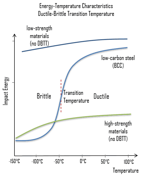
As was written, the distinction between brittleness and ductility isn’t readily apparent, especially because both ductility and brittle behavior are dependent not only on the material in question but also on the temperature (ductile-brittle transition) of the material. The effect of temperature on the nature of the fracture is of considerable importance. Many steels exhibit ductile fracture at elevated temperatures and brittle fracture at low temperatures. The temperature above which a material is ductile and below which it is brittle is known as the ductile–brittle transition temperature (DBTT), nil ductility temperature (NDT), or nil ductility transition temperature. This temperature is not precise, but varies according to prior mechanical and heat treatment and the nature and amounts of impurity elements. It can be determined by some form of drop-weight test (for example, the Charpy or Izod tests).

To minimize neutron fluence:

  • Radial neutron reflectors are installed around the reactor core. Neutron reflectors reduce neutron leakage and therefore they reduce the neutron fluence on a reactor pressure vessel.
  • Core designers design the low leakage loading patterns, in which fresh fuel assemblies are not situated in the peripheral positions of the reactor core.

If the metal is heated to elevated temperatures after irradiation (a form of annealing), it is found that the strength and ductility return to the same values as before irradiation. This means that radiation damage can be annealed out of a  metal.

See also: Ductile-brittle Transition Temperature

See also: Irradiation Embrittlement

See also: Thermal Annealing

References:

Materials Science:

  1. U.S. Department of Energy, Material Science. DOE Fundamentals Handbook, Volume 1 and 2. January 1993.
  2. U.S. Department of Energy, Material Science. DOE Fundamentals Handbook, Volume 2 and 2. January 1993.
  3. William D. Callister, David G. Rethwisch. Materials Science and Engineering: An Introduction 9th Edition, Wiley; 9 edition (December 4, 2013), ISBN-13: 978-1118324578.
  4. Eberhart, Mark (2003). Why Things Break: Understanding the World by the Way It Comes Apart. Harmony. ISBN 978-1-4000-4760-4.
  5. Gaskell, David R. (1995). Introduction to the Thermodynamics of Materials (4th ed.). Taylor and Francis Publishing. ISBN 978-1-56032-992-3.
  6. González-Viñas, W. & Mancini, H.L. (2004). An Introduction to Materials Science. Princeton University Press. ISBN 978-0-691-07097-1.
  7. Ashby, Michael; Hugh Shercliff; David Cebon (2007). Materials: engineering, science, processing and design (1st ed.). Butterworth-Heinemann. ISBN 978-0-7506-8391-3.
  8. J. R. Lamarsh, A. J. Baratta, Introduction to Nuclear Engineering, 3d ed., Prentice-Hall, 2001, ISBN: 0-201-82498-1.

See above:
Power Plant Materials

We hope, this article, Radiation Damage to Metals, helps you. If so, give us a like in the sidebar. Main purpose of this website is to help the public to learn some interesting and important information about materials and their properties.