Measuring Hardness. Many techniques have been developed for obtaining a qualitative measure and a quantitative measure of hardness. Among the most popular are indentation tests, which are based on the ability of a material to withstand surface indentation (localized plastic deformation).
Measuring Hardness
Many techniques have been developed for obtaining a qualitative measure and a quantitative measure of hardness. Among the most popular are indentation tests, which are based on the ability of a material to withstand surface indentation (localized plastic deformation). Those most often used are Brinell, Rockwell, Vickers, Tukon, Sclerscope, and the Leeb rebound hardness test. The first four are based on indentation tests and the fifth on the rebound height of a diamond-tipped metallic hammer. According to the dynamic Leeb principle, hardness value is derived from the energy loss of a defined impact body after impacting on a metal sample, similar to the Shore scleroscope. As a result of many tests, comparisons have been prepared using formulas, tables, and graphs that show the relationships between the results of various hardness tests of specific alloys. There is, however, no exact mathematical relation between any two of the methods.
There are a variety of hardness test methods in common use (e.g. Brinell, Knoop, Vickers and Rockwell). There are tables that are available correlating the hardness numbers from the different test methods where correlation is applicable. In all scales, a high hardness number represents a hard metal.
In industry, hardness tests on metals are used mainly as a check on the quality and uniformity of metals, especially during heat treatment operations. The tests can generally be applied to the finished product without significant damage. Commercial popularity of the Rockwell hardness test arises from its speed, reliability, robustness, resolution and small area of indentation.
References:
Materials Science:
U.S. Department of Energy, Material Science. DOE Fundamentals Handbook, Volume 1 and 2. January 1993.
U.S. Department of Energy, Material Science. DOE Fundamentals Handbook, Volume 2 and 2. January 1993.
William D. Callister, David G. Rethwisch. Materials Science and Engineering: An Introduction 9th Edition, Wiley; 9 edition (December 4, 2013), ISBN-13: 978-1118324578.
Eberhart, Mark (2003). Why Things Break: Understanding the World by the Way It Comes Apart. Harmony. ISBN 978-1-4000-4760-4.
Gaskell, David R. (1995). Introduction to the thermodynamics of Materials (4th ed.). Taylor and Francis Publishing. ISBN 978-1-56032-992-3.
González-Viñas, W. & Mancini, H.L. (2004). An Introduction to Materials Science. Princeton University Press. ISBN 978-0-691-07097-1.
Ashby, Michael; Hugh Shercliff; David Cebon (2007). Materials: engineering, science, processing and design (1st ed.). Butterworth-Heinemann. ISBN 978-0-7506-8391-3.
J. R. Lamarsh, A. J. Baratta, Introduction to Nuclear Engineering, 3d ed., Prentice-Hall, 2001, ISBN: 0-201-82498-1.
See above:
Hardness
We hope, this article, Measuring Hardness – Indentation Tests, helps you. If so, give us a like in the sidebar. Main purpose of this website is to help the public to learn some interesting and important information about materials and their properties.
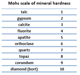
The Mohs scale of mineral hardness is based on the ability of one natural sample of mineral to scratch another mineral visibly. Scratch hardness is the measure of how resistant a sample is to permanent plastic deformation due to friction from a sharp object.
In materials science, hardness is the ability to withstand surface indentation (localized plastic deformation) and scratching. Hardness is probably the most poorly defined material property because it may indicate resistance to scratching, resistance to abrasion, resistance to indentation or even resistance to shaping or localized plastic deformation. Hardness is important from an engineering standpoint because resistance to wear by either friction or erosion by steam, oil, and water generally increases with hardness.
Scratch hardness
Scratch hardness is the measure of how resistant a sample is to permanent plastic deformation due to friction from a sharp object. The most common scale for this qualitative test is Mohs scale, which is used in mineralogy. The Mohs scale of mineral hardness is based on the ability of one natural sample of mineral to scratch another mineral visibly. The hardness of a material is measured against the scale by finding the hardest material that the given material can scratch, or the softest material that can scratch the given material. For example, if some material is scratched by topaz but not by quartz, its hardness on the Mohs scale would fall between 7 and 8.
References:
Materials Science:
U.S. Department of Energy, Material Science. DOE Fundamentals Handbook, Volume 1 and 2. January 1993.
U.S. Department of Energy, Material Science. DOE Fundamentals Handbook, Volume 2 and 2. January 1993.
William D. Callister, David G. Rethwisch. Materials Science and Engineering: An Introduction 9th Edition, Wiley; 9 edition (December 4, 2013), ISBN-13: 978-1118324578.
Eberhart, Mark (2003). Why Things Break: Understanding the World by the Way It Comes Apart. Harmony. ISBN 978-1-4000-4760-4.
Gaskell, David R. (1995). Introduction to the thermodynamics of Materials (4th ed.). Taylor and Francis Publishing. ISBN 978-1-56032-992-3.
González-Viñas, W. & Mancini, H.L. (2004). An Introduction to Materials Science. Princeton University Press. ISBN 978-0-691-07097-1.
Ashby, Michael; Hugh Shercliff; David Cebon (2007). Materials: engineering, science, processing and design (1st ed.). Butterworth-Heinemann. ISBN 978-0-7506-8391-3.
J. R. Lamarsh, A. J. Baratta, Introduction to Nuclear Engineering, 3d ed., Prentice-Hall, 2001, ISBN: 0-201-82498-1.
See above:
Hardness
We hope, this article, Mohs Scale – Scratch Hardness, helps you. If so, give us a like in the sidebar. Main purpose of this website is to help the public to learn some interesting and important information about materials and their properties.
Indentation hardness measures the ability to withstand surface indentation (localized plastic deformation) and the resistance of a sample to material deformation due to a constant compression load from a sharp object.
In materials science, hardness is the ability to withstand surface indentation (localized plastic deformation) and scratching. Hardness is probably the most poorly defined material property because it may indicate resistance to scratching, resistance to abrasion, resistance to indentation or even resistance to shaping or localized plastic deformation. Hardness is important from an engineering standpoint because resistance to wear by either friction or erosion by steam, oil, and water generally increases with hardness.
Indentation hardness
Indentation hardness measures the ability to withstand surface indentation (localized plastic deformation) and the resistance of a sample to material deformation due to a constant compression load from a sharp object. Tests for indentation hardness are primarily used in engineering and metallurgy fields. The traditional methods are based on well-defined physical indentation hardness tests. Very hard indenters of defined geometries and sizes are continuously pressed into the material under a particular force. Deformation parameters, such as the indentation depth in the Rockwell method, are recorded to give measures of hardness. Common indentation hardness scales are Brinell, Rockwell and Vickers.
U.S. Department of Energy, Material Science. DOE Fundamentals Handbook, Volume 1 and 2. January 1993.
U.S. Department of Energy, Material Science. DOE Fundamentals Handbook, Volume 2 and 2. January 1993.
William D. Callister, David G. Rethwisch. Materials Science and Engineering: An Introduction 9th Edition, Wiley; 9 edition (December 4, 2013), ISBN-13: 978-1118324578.
Eberhart, Mark (2003). Why Things Break: Understanding the World by the Way It Comes Apart. Harmony. ISBN 978-1-4000-4760-4.
Gaskell, David R. (1995). Introduction to the thermodynamics of Materials (4th ed.). Taylor and Francis Publishing. ISBN 978-1-56032-992-3.
González-Viñas, W. & Mancini, H.L. (2004). An Introduction to Materials Science. Princeton University Press. ISBN 978-0-691-07097-1.
Ashby, Michael; Hugh Shercliff; David Cebon (2007). Materials: engineering, science, processing and design (1st ed.). Butterworth-Heinemann. ISBN 978-0-7506-8391-3.
J. R. Lamarsh, A. J. Baratta, Introduction to Nuclear Engineering, 3d ed., Prentice-Hall, 2001, ISBN: 0-201-82498-1.
See above:
Hardness
We hope, this article, Indentation hardness, helps you. If so, give us a like in the sidebar. Main purpose of this website is to help the public to learn some interesting and important information about materials and their properties.
There are three main types of hardness measurements: Scratch hardness, indentation hardness and rebound hardness. Hardness is probably the most poorly defined material property because it may indicate resistance to scratching, resistance to abrasion, resistance to indentation or even resistance to shaping or localized plastic deformation.
In materials science, hardness is the ability to withstand surface indentation (localized plastic deformation) and scratching. Hardness is probably the most poorly defined material property because it may indicate resistance to scratching, resistance to abrasion, resistance to indentation or even resistance to shaping or localized plastic deformation. Hardness is important from an engineering standpoint because resistance to wear by either friction or erosion by steam, oil, and water generally increases with hardness.
There are three main types of hardness measurements:
Scratch hardness. Scratch hardness is the measure of how resistant a sample is to permanent plastic deformation due to friction from a sharp object. The most common scale for this qualitative test is Mohs scale, which is used in mineralogy. The Mohs scale of mineral hardness is based on the ability of one natural sample of mineral to scratch another mineral visibly. The hardness of a material is measured against the scale by finding the hardest material that the given material can scratch, or the softest material that can scratch the given material. For example, if some material is scratched by topaz but not by quartz, its hardness on the Mohs scale would fall between 7 and 8.
Indentation hardness. Indentation hardness measures the ability to withstand surface indentation (localized plastic deformation) and the resistance of a sample to material deformation due to a constant compression load from a sharp object. Tests for indentation hardness are primarily used in engineering and metallurgy fields. The traditional methods are based on well-defined physical indentation hardness tests. Very hard indenters of defined geometries and sizes are continuously pressed into the material under a particular force. Deformation parameters, such as the indentation depth in the Rockwell method, are recorded to give measures of hardness. Common indentation hardness scales are Brinell, Rockwell and Vickers.
Rebound hardness. Rebound hardness, also known as dynamic hardness, measures the height of the “bounce” of a diamond-tipped hammer dropped from a fixed height onto a material. One of devices used to take this measurement is known as a scleroscope. It consists of a steel ball dropped from a fixed height. This type of hardness is related to elasticity.
Within each of these classes of measurement there are individual measurement scales. For practical reasons conversion tables are used to convert between one scale and another.
References:
Materials Science:
U.S. Department of Energy, Material Science. DOE Fundamentals Handbook, Volume 1 and 2. January 1993.
U.S. Department of Energy, Material Science. DOE Fundamentals Handbook, Volume 2 and 2. January 1993.
William D. Callister, David G. Rethwisch. Materials Science and Engineering: An Introduction 9th Edition, Wiley; 9 edition (December 4, 2013), ISBN-13: 978-1118324578.
Eberhart, Mark (2003). Why Things Break: Understanding the World by the Way It Comes Apart. Harmony. ISBN 978-1-4000-4760-4.
Gaskell, David R. (1995). Introduction to the thermodynamics of Materials (4th ed.). Taylor and Francis Publishing. ISBN 978-1-56032-992-3.
González-Viñas, W. & Mancini, H.L. (2004). An Introduction to Materials Science. Princeton University Press. ISBN 978-0-691-07097-1.
Ashby, Michael; Hugh Shercliff; David Cebon (2007). Materials: engineering, science, processing and design (1st ed.). Butterworth-Heinemann. ISBN 978-0-7506-8391-3.
J. R. Lamarsh, A. J. Baratta, Introduction to Nuclear Engineering, 3d ed., Prentice-Hall, 2001, ISBN: 0-201-82498-1.
See above:
Hardness
We hope, this article, Types of Hardness – Materials, helps you. If so, give us a like in the sidebar. Main purpose of this website is to help the public to learn some interesting and important information about materials and their properties.
Units of hardness. There are a variety of hardness test methods in common use (e.g. Brinell, Knoop, Vickers and Rockwell). There are tables that are available correlating the hardness numbers from the different test methods where correlation is applicable.
In materials science, hardness is the ability to withstand surface indentation (localized plastic deformation) and scratching. Hardness is probably the most poorly defined material property because it may indicate resistance to scratching, resistance to abrasion, resistance to indentation or even resistance to shaping or localized plastic deformation. Hardness is important from an engineering standpoint because resistance to wear by either friction or erosion by steam, oil, and water generally increases with hardness.
There are three main types of hardness measurements:
Scratch hardness. Scratch hardness is the measure of how resistant a sample is to permanent plastic deformation due to friction from a sharp object. The most common scale for this qualitative test is Mohs scale, which is used in mineralogy. The Mohs scale of mineral hardness is based on the ability of one natural sample of mineral to scratch another mineral visibly. The hardness of a material is measured against the scale by finding the hardest material that the given material can scratch, or the softest material that can scratch the given material. For example, if some material is scratched by topaz but not by quartz, its hardness on the Mohs scale would fall between 7 and 8.
Indentation hardness. Indentation hardness measures the ability to withstand surface indentation (localized plastic deformation) and the resistance of a sample to material deformation due to a constant compression load from a sharp object. Tests for indentation hardness are primarily used in engineering and metallurgy fields. The traditional methods are based on well-defined physical indentation hardness tests. Very hard indenters of defined geometries and sizes are continuously pressed into the material under a particular force. Deformation parameters, such as the indentation depth in the Rockwell method, are recorded to give measures of hardness. Common indentation hardness scales are Brinell, Rockwell and Vickers.
Rebound hardness. Rebound hardness, also known as dynamic hardness, measures the height of the “bounce” of a diamond-tipped hammer dropped from a fixed height onto a material. One of devices used to take this measurement is known as a scleroscope. It consists of a steel ball dropped from a fixed height. This type of hardness is related to elasticity.
Within each of these classes of measurement there are individual measurement scales. For practical reasons conversion tables are used to convert between one scale and another.
Hardness Numbers – Brinell
Brinell hardness test is one of indentation hardness tests, that has been developed for hardness testing. In Brinell tests, a hard, spherical indenter is forced under a specific load into the surface of the metal to be tested. The typical test uses a 10 mm (0.39 in) diameter hardened steel ball as an indenter with a 3,000 kgf (29.42 kN; 6,614 lbf) force. The load is maintained constant for a specified time (between 10 and 30 s). For softer materials, a smaller force is used; for harder materials, a tungsten carbide ball is substituted for the steel ball.
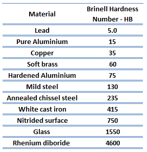
The test provides numerical results to quantify the hardness of a material, which is expressed by the Brinell hardness number – HB. The Brinell hardness number is designated by the most commonly used test standards (ASTM E10-14[2] and ISO 6506–1:2005) as HBW (H from hardness, B from brinell and W from the material of the indenter, tungsten (wolfram) carbide). In former standards HB or HBS were used to refer to measurements made with steel indenters.
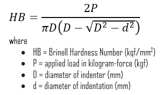
The Brinell hardness number (HB) is the load divided by the surface area of the indentation. The diameter of the impression is measured with a microscope with a superimposed scale. The Brinell hardness number is computed from the equation:
There are a variety of test methods in common use (e.g. Brinell, Knoop, Vickers and Rockwell). There are tables that are available correlating the hardness numbers from the different test methods where correlation is applicable. In all scales, a high hardness number represents a hard metal.
Besides the correlation between different hardness numbers, there are also some correlations possible with other material properties. For example, for heat-treated plain carbon steels and medium alloy steels, another convenient conversion is that of Brinell hardness to ultimate tensile strength. In this case, the ultimate tensile strength (in psi) approximately equals the Brinell Hardness Number multiplied by 500. Generally, a high hardness will indicate a relatively high strength and low ductility in the material.
In industry, hardness tests on metals are used mainly as a check on the quality and uniformity of metals, especially during heat treatment operations. The tests can generally be applied to the finished product without significant damage.
Hardness Numbers – Vickers
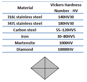
The Vickers hardness test method was developed by Robert L. Smith and George E. Sandland at Vickers Ltd as an alternative to the Brinell method to measure the hardness of materials. The Vickers hardness test method can be also used as a microhardness test method, which is mostly used for small parts, thin sections, or case depth work. Since the test indentation is very small in a Vickers microhardness test, it is useful for a variety of applications such as: testing very thin materials like foils or measuring the surface of a part, small parts or small areas.
The Vickers method is based on an optical measurement system. The Microhardness test procedure, ASTM E-384, specifies a range of light loads using a diamond indenter to make an indentation which is measured and converted to a hardness value. The Vickers test is often easier to use than other hardness tests since the required calculations are independent of the size of the indenter, and the indenter can be used for all materials irrespective of hardness. A square base pyramid shaped diamond is used for testing in the Vickers scale. For microindentation typical loads are very light, ranging from 10gf to 1kgf, although macroindentation Vickers loads can range up to 30 kg or more.
Hardness Numbers and Conversion
There are a variety of hardness test methods in common use (e.g. Brinell, Knoop, Vickers and Rockwell). There are tables that are available correlating the hardness numbers from the different test methods where correlation is applicable. In all scales, a high hardness number represents a hard metal.
In industry, hardness tests on metals are used mainly as a check on the quality and uniformity of metals, especially during heat treatment operations. The tests can generally be applied to the finished product without significant damage. Commercial popularity of the Rockwell hardness test arises from its speed, reliability, robustness, resolution and small area of indentation.
References:
Materials Science:
U.S. Department of Energy, Material Science. DOE Fundamentals Handbook, Volume 1 and 2. January 1993.
U.S. Department of Energy, Material Science. DOE Fundamentals Handbook, Volume 2 and 2. January 1993.
William D. Callister, David G. Rethwisch. Materials Science and Engineering: An Introduction 9th Edition, Wiley; 9 edition (December 4, 2013), ISBN-13: 978-1118324578.
Eberhart, Mark (2003). Why Things Break: Understanding the World by the Way It Comes Apart. Harmony. ISBN 978-1-4000-4760-4.
Gaskell, David R. (1995). Introduction to the thermodynamics of Materials (4th ed.). Taylor and Francis Publishing. ISBN 978-1-56032-992-3.
González-Viñas, W. & Mancini, H.L. (2004). An Introduction to Materials Science. Princeton University Press. ISBN 978-0-691-07097-1.
Ashby, Michael; Hugh Shercliff; David Cebon (2007). Materials: engineering, science, processing and design (1st ed.). Butterworth-Heinemann. ISBN 978-0-7506-8391-3.
J. R. Lamarsh, A. J. Baratta, Introduction to Nuclear Engineering, 3d ed., Prentice-Hall, 2001, ISBN: 0-201-82498-1.
See above:
Hardness
We hope, this article, Units of Hardness – Hardness Numbers, helps you. If so, give us a like in the sidebar. Main purpose of this website is to help the public to learn some interesting and important information about materials and their properties.
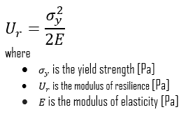
The modulus of resilience, Ur, which is defined as the maximum energy that can be absorbed per unit volume without creating a permanent distortion.
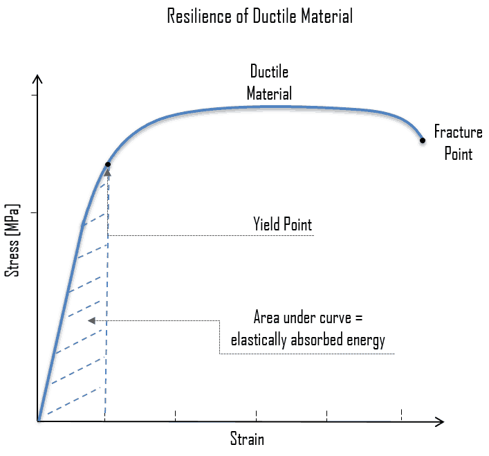
In materials science, resilience is the ability and the capacity of a material to absorb energy when it is deformed elastically and then, upon unloading, to recover this amount of energy. The maximum energy that can be absorbed up to the elastic limit, without creating a permanent deformation is known as proof resilience. In the stress-strain curve, it is given by the area under the portion of a stress–strain curve (up to yield point).
Under assumption of linear elasticity or up to proportional limit, resilience can be calculated by integrating the stress–strain curve from zero to the proportional limit.
The associated property is the modulus of resilience, Ur, which is defined as the maximum energy that can be absorbed per unit volume without creating a permanent distortion. It is the strain energy per unit volume required to stress a material from an unloaded state up to the point of yielding. This analysis is not valid for non-linear elastic materials like rubber, for which the approach of area under the curve till elastic limit must be used.
Thus, resilient materials are those having high yield strengths and low moduli of elasticity such alloys are used in spring applications. The energy expended in deforming the spring is stored in it and can be recovered when the spring returns to its original shape.
References:
Materials Science:
U.S. Department of Energy, Material Science. DOE Fundamentals Handbook, Volume 1 and 2. January 1993.
U.S. Department of Energy, Material Science. DOE Fundamentals Handbook, Volume 2 and 2. January 1993.
William D. Callister, David G. Rethwisch. Materials Science and Engineering: An Introduction 9th Edition, Wiley; 9 edition (December 4, 2013), ISBN-13: 978-1118324578.
Eberhart, Mark (2003). Why Things Break: Understanding the World by the Way It Comes Apart. Harmony. ISBN 978-1-4000-4760-4.
Gaskell, David R. (1995). Introduction to the thermodynamics of Materials (4th ed.). Taylor and Francis Publishing. ISBN 978-1-56032-992-3.
González-Viñas, W. & Mancini, H.L. (2004). An Introduction to Materials Science. Princeton University Press. ISBN 978-0-691-07097-1.
Ashby, Michael; Hugh Shercliff; David Cebon (2007). Materials: engineering, science, processing and design (1st ed.). Butterworth-Heinemann. ISBN 978-0-7506-8391-3.
J. R. Lamarsh, A. J. Baratta, Introduction to Nuclear Engineering, 3d ed., Prentice-Hall, 2001, ISBN: 0-201-82498-1.
See above:
Resilience
We hope, this article, Modulus of Resilience, helps you. If so, give us a like in the sidebar. Main purpose of this website is to help the public to learn some interesting and important information about materials and their properties.
In materials science, hardness is the ability to withstand surface indentation (localized plastic deformation) and scratching. Hardness is probably the most poorly defined material property because it may indicate resistance to scratching, resistance to abrasion, resistance to indentation or even resistance to shaping or localized plastic deformation.
In materials science, hardness is the ability to withstand surface indentation (localized plastic deformation) and scratching. Hardness is probably the most poorly defined material property because it may indicate resistance to scratching, resistance to abrasion, resistance to indentation or even resistance to shaping or localized plastic deformation. Hardness is important from an engineering standpoint because resistance to wear by either friction or erosion by steam, oil, and water generally increases with hardness.
There are three main types of hardness measurements:
Scratch hardness. Scratch hardness is the measure of how resistant a sample is to permanent plastic deformation due to friction from a sharp object. The most common scale for this qualitative test is Mohs scale, which is used in mineralogy. The Mohs scale of mineral hardness is based on the ability of one natural sample of mineral to scratch another mineral visibly. The hardness of a material is measured against the scale by finding the hardest material that the given material can scratch, or the softest material that can scratch the given material. For example, if some material is scratched by topaz but not by quartz, its hardness on the Mohs scale would fall between 7 and 8.
Indentation hardness. Indentation hardness measures the ability to withstand surface indentation (localized plastic deformation) and the resistance of a sample to material deformation due to a constant compression load from a sharp object. Tests for indentation hardness are primarily used in engineering and metallurgy fields. The traditional methods are based on well-defined physical indentation hardness tests. Very hard indenters of defined geometries and sizes are continuously pressed into the material under a particular force. Deformation parameters, such as the indentation depth in the Rockwell method, are recorded to give measures of hardness. Common indentation hardness scales are Brinell, Rockwell and Vickers.
Rebound hardness. Rebound hardness, also known as dynamic hardness, measures the height of the “bounce” of a diamond-tipped hammer dropped from a fixed height onto a material. One of devices used to take this measurement is known as a scleroscope. It consists of a steel ball dropped from a fixed height. This type of hardness is related to elasticity.
Within each of these classes of measurement there are individual measurement scales. For practical reasons conversion tables are used to convert between one scale and another.
Measuring Hardness
Many techniques have been developed for obtaining a qualitative measure and a quantitative measure of hardness. Among the most popular are indentation tests, which are based on the ability of a material to withstand surface indentation (localized plastic deformation). Those most often used are Brinell, Rockwell, Vickers, Tukon, Sclerscope, and the Leeb rebound hardness test. The first four are based on indentation tests and the fifth on the rebound height of a diamond-tipped metallic hammer. According to the dynamic Leeb principle, hardness value is derived from the energy loss of a defined impact body after impacting on a metal sample, similar to the Shore scleroscope. As a result of many tests, comparisons have been prepared using formulas, tables, and graphs that show the relationships between the results of various hardness tests of specific alloys. There is, however, no exact mathematical relation between any two of the methods.
Brinell Hardness Test
Brinell hardness test is one of indentation hardness tests, that has been developed for hardness testing. In Brinell tests, a hard, spherical indenter is forced under a specific load into the surface of the metal to be tested. The typical test uses a 10 mm (0.39 in) diameter hardened steel ball as an indenter with a 3,000 kgf (29.42 kN; 6,614 lbf) force. The load is maintained constant for a specified time (between 10 and 30 s). For softer materials, a smaller force is used; for harder materials, a tungsten carbide ball is substituted for the steel ball.
The test provides numerical results to quantify the hardness of a material, which is expressed by the Brinell hardness number – HB. The Brinell hardness number is designated by the most commonly used test standards (ASTM E10-14[2] and ISO 6506–1:2005) as HBW (H from hardness, B from brinell and W from the material of the indenter, tungsten (wolfram) carbide). In former standards HB or HBS were used to refer to measurements made with steel indenters.
The Brinell hardness number (HB) is the load divided by the surface area of the indentation. The diameter of the impression is measured with a microscope with a superimposed scale. The Brinell hardness number is computed from the equation:
There are a variety of test methods in common use (e.g. Brinell, Knoop, Vickers and Rockwell). There are tables that are available correlating the hardness numbers from the different test methods where correlation is applicable. In all scales, a high hardness number represents a hard metal.
Besides the correlation between different hardness numbers, there are also some correlations possible with other material properties. For example, for heat-treated plain carbon steels and medium alloy steels, another convenient conversion is that of Brinell hardness to ultimate tensile strength. In this case, the ultimate tensile strength (in psi) approximately equals the Brinell Hardness Number multiplied by 500. Generally, a high hardness will indicate a relatively high strength and low ductility in the material.
In industry, hardness tests on metals are used mainly as a check on the quality and uniformity of metals, especially during heat treatment operations. The tests can generally be applied to the finished product without significant damage.
Rockwell Hardness Test
Rockwell hardness test is one of the most common indentation hardness tests, that has been developed for hardness testing. In contrast to Brinell test, the Rockwell tester measures the depth of penetration of an indenter under a large load (major load) compared to the penetration made by a preload (minor load). The minor load establishes the zero position. The major load is applied, then removed while still maintaining the minor load. The difference between depth of penetration before and after application of the major load is used to calculate the Rockwell hardness number. That is, the penetration depth and hardness are inversely proportional. The chief advantage of Rockwell hardness is its ability to display hardness values directly. The result is a dimensionless number noted as HRA, HRB, HRC, etc., where the last letter is the respective Rockwell scale.
Several different scales may be used from possible combinations of various indenters and different loads a process that permits the testing of virtually all metal alloys. The test provides results to quantify the hardness of a material, which is expressed by the Rockwell hardness number – HR, which is directly displayed on the dial. The various indenter types combined with a range of test loads form a matrix of Rockwell hardness scales that are applicable to a wide variety of materials. Rockwell B and Rockwell C are the typical tests in this facility. The Rockwell B penetrator is a 1.59mm (1/16 inch) diameter tungsten-carbide ball and the major load is 100kg. The Rockwell C test is performed with a Brale penetrator (120°diamond cone) and a major load of 150kg.
Each Rockwell hardness scale is identified by a letter designation indicative of the indenter type and the major and minor loads used for the test. The Rockwell hardness number is expressed as a combination of the measured numerical hardness value and the scale letter preceded by the letters, HR.
There are a variety of hardness test methods in common use (e.g. Brinell, Knoop, Vickers and Rockwell). There are tables that are available correlating the hardness numbers from the different test methods where correlation is applicable. In all scales, a high hardness number represents a hard metal.
In industry, hardness tests on metals are used mainly as a check on the quality and uniformity of metals, especially during heat treatment operations. The tests can generally be applied to the finished product without significant damage. Commercial popularity of the Rockwell hardness test arises from its speed, reliability, robustness, resolution and small area of indentation.
Vickers Hardness Test
The Vickers hardness test method was developed by Robert L. Smith and George E. Sandland at Vickers Ltd as an alternative to the Brinell method to measure the hardness of materials. The Vickers hardness test method can be also used as a microhardness test method, which is mostly used for small parts, thin sections, or case depth work. Since the test indentation is very small in a Vickers microhardness test, it is useful for a variety of applications such as: testing very thin materials like foils or measuring the surface of a part, small parts or small areas.
The Vickers method is based on an optical measurement system. The Microhardness test procedure, ASTM E-384, specifies a range of light loads using a diamond indenter to make an indentation which is measured and converted to a hardness value. The Vickers test is often easier to use than other hardness tests since the required calculations are independent of the size of the indenter, and the indenter can be used for all materials irrespective of hardness. A square base pyramid shaped diamond is used for testing in the Vickers scale. For microindentation typical loads are very light, ranging from 10gf to 1kgf, although macroindentation Vickers loads can range up to 30 kg or more.
Knoop Hardness Test
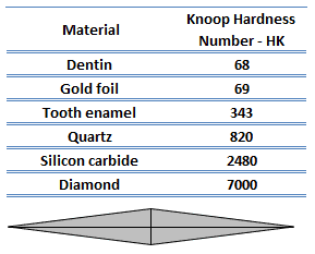
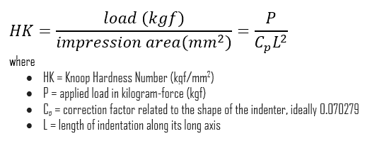
The Knoop hardness test method is one of microhardness tests – tests for mechanical hardness used particularly for very brittle materials or thin sheets, where only a small indentation may be made for testing purposes. The Knoop and Vickers techniques are referred to as microindentation-testing methods on the basis of indenter size. Both are well suited for measuring the hardness of small, selected specimen regions; furthermore, the Knoop technique is used for testing brittle materials such as ceramics. The geometry of this indenter is an extended pyramid with the length to width ratio being 7:1 and respective face angles are 172 degrees for the long edge and 130 degrees for the short edge.
The Knoop and Vickers hardness numbers are designated by HK and HV, respectively, and hardness scales for both techniques are approximately equivalent. The Knoop hardness number HK or is given by the formula:
Hardness Numbers and Conversion
There are a variety of hardness test methods in common use (e.g. Brinell, Knoop, Vickers and Rockwell). There are tables that are available correlating the hardness numbers from the different test methods where correlation is applicable. In all scales, a high hardness number represents a hard metal.
In industry, hardness tests on metals are used mainly as a check on the quality and uniformity of metals, especially during heat treatment operations. The tests can generally be applied to the finished product without significant damage. Commercial popularity of the Rockwell hardness test arises from its speed, reliability, robustness, resolution and small area of indentation.
Hardness and Tensile Strength
Besides the correlation between different hardness numbers, there are also some correlations possible with other material properties. For example, for heat-treated plain carbon steels and medium alloy steels, another convenient conversion is that of Brinell hardness to ultimate tensile strength. In this case, the ultimate tensile strength (in psi) approximately equals the Brinell Hardness Number multiplied by 500. Generally, a high hardness will indicate a relatively high strength and low ductility in the material.
In industry, hardness tests on metals are used mainly as a check on the quality and uniformity of metals, especially during heat treatment operations. The tests can generally be applied to the finished product without significant damage.
References:
Materials Science:
U.S. Department of Energy, Material Science. DOE Fundamentals Handbook, Volume 1 and 2. January 1993.
U.S. Department of Energy, Material Science. DOE Fundamentals Handbook, Volume 2 and 2. January 1993.
William D. Callister, David G. Rethwisch. Materials Science and Engineering: An Introduction 9th Edition, Wiley; 9 edition (December 4, 2013), ISBN-13: 978-1118324578.
Eberhart, Mark (2003). Why Things Break: Understanding the World by the Way It Comes Apart. Harmony. ISBN 978-1-4000-4760-4.
Gaskell, David R. (1995). Introduction to the thermodynamics of Materials (4th ed.). Taylor and Francis Publishing. ISBN 978-1-56032-992-3.
González-Viñas, W. & Mancini, H.L. (2004). An Introduction to Materials Science. Princeton University Press. ISBN 978-0-691-07097-1.
Ashby, Michael; Hugh Shercliff; David Cebon (2007). Materials: engineering, science, processing and design (1st ed.). Butterworth-Heinemann. ISBN 978-0-7506-8391-3.
J. R. Lamarsh, A. J. Baratta, Introduction to Nuclear Engineering, 3d ed., Prentice-Hall, 2001, ISBN: 0-201-82498-1.
See above:
Material Properties
We hope, this article, Hardness, helps you. If so, give us a like in the sidebar. Main purpose of this website is to help the public to learn some interesting and important information about materials and their properties.
In materials science, brittleness is understood as the lack of ductility. For engineers, the understanding of the difference between brittle and ductile material is of the highest importance.
In materials science, brittleness is understood as the lack of ductility. For engineers, the understanding of the difference between brittle and ductile material is of the highest importance. There are fractures (e.g. brittle fracture), which occur under specific conditions without warning and can cause major damage to materials. Brittle fracture occurs suddenly and catastrophically without any warning. This is a consequence of the spontaneous and rapid crack propagation. A detailed understanding of how fracture occurs in materials may be assisted by the study of fracture mechanics.
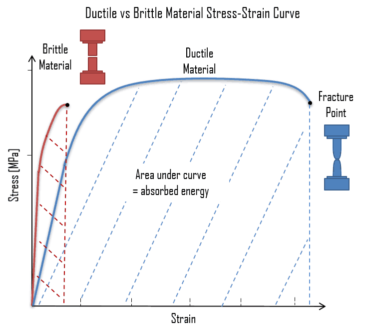
In the tensile test, the fracture point is the point of strain where the material physically separates. At this point, the strain reaches its maximum value and the material actually fractures, even though the corresponding stress may be less than the ultimate strength at this point. Ductile materials have a fracture strength lower than the ultimate tensile strength (UTS), whereas in brittle materials the fracture strength is equivalent to the UTS. If a ductile material reaches its ultimate tensile strength in a load-controlled situation, it will continue to deform, with no additional load application, until it ruptures. However, if the loading is displacement-controlled, the deformation of the material may relieve the load, preventing rupture. It is possible to distinguish some common characteristics among the stress–strain curves of various groups of materials.
Fracture of Material
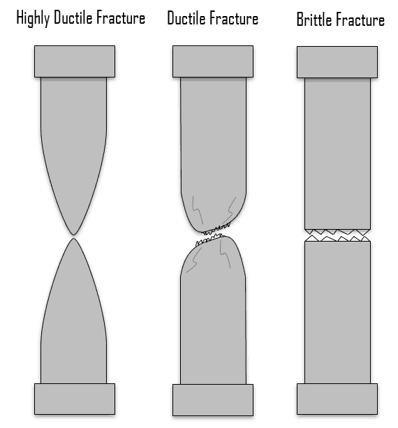
A fracture is the separation of an object or material into two or more pieces under the action of stress. Engineers need to understand fracture mechanisms. There are fractures (e.g. brittle fracture), which occur under specific conditions without warning and can cause major damage to materials. Brittle fracture occurs suddenly and catastrophically without any warning. This is a consequence of the spontaneous and rapid crack propagation. However, for ductile fracture, the presence of plastic deformation gives warning that failure is imminent, allowing preventive measures to be taken. A detailed understanding of how fracture occurs in materials may be assisted by the study of fracture mechanics.
In the tensile test, the fracture point is the point of strain where the material physically separates. At this point, the strain reaches its maximum value and the material actually fractures, even though the corresponding stress may be less than the ultimate strength at this point. Ductile materials have a fracture strength lower than the ultimate tensile strength (UTS), whereas in brittle materials the fracture strength is equivalent to the UTS. If a ductile material reaches its ultimate tensile strength in a load-controlled situation, it will continue to deform, with no additional load application, until it ruptures. However, if the loading is displacement-controlled, the deformation of the material may relieve the load, preventing rupture. It is possible to distinguish some common characteristics among the stress–strain curves of various groups of materials. On this basis, it is possible to divide materials into two broad categories; namely:
Ductile Materials. Ductility is the ability of a material to be elongated in tension. Ductile material will deform (elongate) more than brittle material. Ductile materials show large deformation before fracture. In ductile fracture, extensive plastic deformation (necking) takes place before fracture. Ductile fracture (shear fracture) is better than brittle fracture, because there is slow propagation and an absorption of a large amount energy before fracture. Any fracture process involves two steps, crack formation and propagation, in response to an imposed stress. The mode of fracture is highly dependent on the mechanism of crack propagation. Cracks in ductile materials are said to be stable (i.e., resist extension without an increase in applied stress). For brittle materials, cracks are unstable. That means crack propagation, once started, continues spontaneously without an increase in stress level. Ductility is desirable in the high temperature and high pressure applications in reactor plants because of the added stresses on the metals. High ductility in these applications helps prevent brittle fracture.
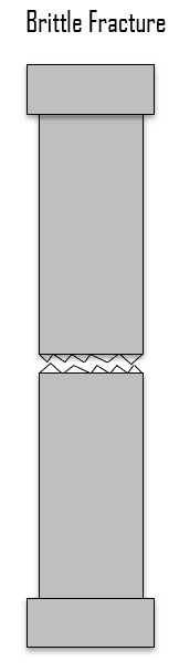
Brittle Materials. Brittle materials, when subjected to stress, break with little elastic deformation and without significant plastic deformation. Brittle materials absorb relatively little energy prior to fracture, even those of high strength. In brittle fracture (transgranular cleavage), no apparent plastic deformation takes place before fracture. In crystalography, cleavage is the tendency of crystalline materials to split along definite crystallographic structural planes. Any fracture process involves two steps, crack formation and propagation, in response to an imposed stress. The mode of fracture is highly dependent on the mechanism of crack propagation. For brittle materials, cracks are unstable. That means crack propagation, once started, continues spontaneously without an increase in stress level. Cracks propagate rapidly (speed of sound) and occurs at high speeds – up to 2133.6 m/s in steel. It should be noted that smaller grain size, higher temperature, and lower stress tend to mitigate crack initiation. Larger grain size, lower temperatures, and higher stress tend to favor crack propagation. There is a stress level below which a crack will not propagate at any temperature. This is called the lower fracture propagation stress. For brittle fracture, the fracture surface is relatively flat and perpendicular to the direction of the applied tensile load. In general, brittle fracture requires three conditions:
Flaw such as a crack
Stress sufficient to develop a small deformation at the crack tip
Temperature at or below DBTT
Ductile–brittle Transition Temperature
Brittle fracture of the U.S. Liberty Ship Esso Manhattan
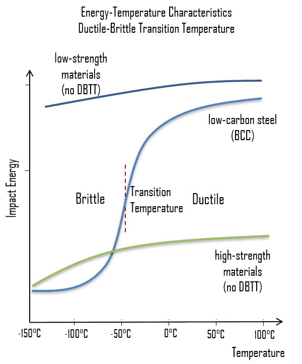
As was written, the distinction between brittleness and ductility isn’t readily apparent, especially because both ductility and brittle behavior are dependent not only on the material in question but also on the temperature (ductile-brittle transition) of the material. The effect of temperature on the nature of the fracture is of considerable importance. Many steels exhibit ductile fracture at elevated temperatures and brittle fracture at low temperatures. The temperature above which a material is ductile and below which it is brittle is known as the ductile–brittle transition temperature (DBTT), nil ductility temperature (NDT), or nil ductility transition temperature. This temperature is not precise, but varies according to prior mechanical and heat treatment and the nature and amounts of impurity elements. It can be determined by some form of drop-weight test (for example, the Charpy or Izod tests).
The ductile–brittle transition temperature (DBTT) is the temperature at which the fracture energy passes below a predetermined value (e.g. 40 J for a standard Charpy impact test). Ductility is an essential requirement for steels used in the construction of reactor components, such as the reactor vessel. Therefore, the DBTT is of significance in the operation of these vessels. In this case, the size of the grain determines the properties of the metal. For example, smaller grain size increases tensile strength, tends to increase ductility and results in a decrease in DBTT. Grain size is controlled by heat treatment in the specifications and manufacturing of reactor vessels. The DBTT can also be lowered by small additions of selected alloying elements such as nickel and manganese to low-carbon steels.
Typically, the low alloy reactor pressure vessel steels are ferritic steels that exhibit the classic ductile-to-brittle transition behaviour with decreasing temperature. This transitional temperature is of the highest importance during plant heatup.
Failure modes:
Low toughness region: Main failure mode is the brittle fracture (transgranular cleavage). In brittle fracture, no apparent plastic deformation takes place before fracture. Cracks propagate rapidly.
High toughness region: Main failure mode is the ductile fracture (shear fracture). In ductile fracture, extensive plastic deformation (necking) takes place before fracture. Ductile fracture is better than brittle fracture, because there is slow propagation and an absorption of a large amount energy before fracture.
In some materials, the transition is sharper than others and typically requires a temperature-sensitive deformation mechanism. For example, in materials with a body-centered cubic (bcc) lattice the DBTT is readily apparent, as the motion of screw dislocations is very temperature sensitive because the rearrangement of the dislocation core prior to slip requires thermal activation. This can be problematic for steels with a high ferrite content. This famously resulted in serious hull cracking in Liberty ships in colder waters during World War II, causing many sinkings. The vessels were constructed of a steel alloy that possessed adequate toughness according to room-temperature tensile tests. The brittle fractures occurred at relatively low ambient temperatures, at about 4°C (40°F), in the vicinity of the transition temperature of the alloy. It must be noted that low-strength FCC metals (e.g. copper alloys) and most HCP metals do not experience a ductile-to-brittle transition and retain tough also for lower temperatures. On the other hand, many high-strength metals (e.g. very high-strength steels) also do not experience a ductile-to-brittle transition, but, in this case, they remain very brittle.
DBTT can also be influenced by external factors such as neutron radiation, which leads to an increase in internal lattice defects and a corresponding decrease in ductility and increase in DBTT.
Irradiation Embrittlement
During the operation of a nuclear power plant, the material of the reactor pressure vessel and the material of other reactor internals are exposed to neutron radiation (especially to fast neutrons >0.5MeV), which results in localized embrittlement of the steel and welds in the area of the reactor core. This phenomenon, known as irradiation embrittlment, results in the steadily increase in DBTT. It is not likely that the DBTT will approach the normal operating temperature of the steel. However, there is a possibility that when the reactor is being shut down or during an abnormal cooldown, the temperature may fall below the DBTT value while the internal pressure is still high. Therefore nuclear regulators require that a reactor vessel material surveillance program be conducted in watercooled power reactors.
Irradiation embrittlement can lead to loss of fracture toughness. Typically, the low alloy reactor pressure vessel steels are ferritic steels that exhibit the classic ductile-to-brittle transition behaviour with decreasing temperature. This transitional temperature is of the highest importance during plant heatup.
Failure modes:
Low toughness region: Main failure mode is the brittle fracture (transgranular cleavage). In brittle fracture, no apparent plastic deformation takes place before fracture. Cracks propagate rapidly.
High toughness region: Main failure mode is the ductile fracture (shear fracture). In ductile fracture, extensive plastic deformation (necking) takes place before fracture. Ductile fracture is better than brittle fracture, because there is slow propagation and an absorption of a large amount energy before fracture.
Neutron irradiation tends to increase the temperature (ductile-to-brittle transition temperature) at which this transition occurs and tends to decrease the ductile toughness.
Stress Corrosion Cracking
One of the most serious metallurgical problems and one that is a major concern in the nuclear industry is stress-corrosion cracking (SCC). Stress-corrosion cracking results from the combined action of an applied tensile stress and a corrosive environment, both influences are necessary. SCC is a type of intergranular attack corrosion that occurs at the grain boundaries under tensile stress. It tends to propagate as stress opens cracks that are subject to corrosion, which are then corroded further, weakening the metal by further cracking. The cracks can follow intergranular or transgranular paths, and there is often a tendency for crack branching. Failure behavior is characteristic of that for a brittle material, even though the metal alloy is intrinsically ductile. SCC can lead to unexpected sudden failure of normally ductile metal alloys subjected to a tensile stress, especially at elevated temperature. SCC is highly chemically specific in that certain alloys are likely to undergo SCC only when exposed to a small number of chemical environments.
The most effective means of preventing SCC in reactor systems are:
designing properly
reducing stress
removing critical environmental species such as hydroxides, chlorides, and oxygen
avoiding stagnant areas and crevices in heat exchangers where chloride and hydroxide might become concentrated.
Stress-corrosion cracking may cause, for example, a failure of nuclear fuel rod after inappropriate power changes, rod movement and plant startup. Certain austenitic stainless steels and aluminium alloys crack in the presence of chlorides and mild steel cracks in the presence of alkali (boiler cracking). Low alloy steels are less susceptible than high alloy steels, but they are subject to SCC in water containing chloride ions. Nickel-based alloys, however, are not effected by chloride or hydroxide ions. An example of a nickel-based alloy that is resistant to stress-corrosion cracking is inconel.
Special Reference: U.S. Department of Energy, Material Science. DOE Fundamentals Handbook, Volume 1 and 2. January 1993.
Stress-corrosion Cracking as Fuel Failure Mechanism
Cladding prevents radioactive fission products from escaping the fuel matrix into the reactor coolant and contaminating it. There are various fuel failure root causes, that have been identified in past. In the early dates of PWR and BWR operations, these causes were predominantly fabrication defects or fretting. One of possible causes is also the pellet-cladding interaction (PCI), which may be caused by stress-corrosion cracking. Stress-corrosion cracking may cause, for example, a failure of nuclear fuel rod after inappropriate power changes, rod movement and plant startup.
In nominal operating conditions, pellet temperature stands at about 1,000° C at the center, 400–500° C at the periphery. In the event of a major increase in power, temperature at the pellet center rises steeply (> 1,500° C, or even > 2,000° C). In this case, a difference in thermal expansions between fuel cladding and fuel pellets causes an increase in stress in the fuel cladding. PCI fuel failure is caused by stress-corrosion cracking on the inside surface of the cladding, which results from the combined effects of fuel pellet expansion (especially at pellet radial cracks and the presence of an aggressive fission product environment (especially gaseous iodine). Such a failure is found to occur, experimentally, after from one to a few minutes’ holding time, at sustained high power levels.
Special Reference: CEA, Nuclear Energy Division. Nuclear Fuels, ISBN 978-2-281-11345-7
Hydrogen Embrittlement
Hydrogen embrittlement is one of many forms of stress-corrosion cracking. Hydrogen embrittlement results from the combined action of an applied tensile stress and a corrosive hydrogen environment, both influences are necessary. In this case the corrosive agent is hydrogen in its atomic form (H as opposed to the molecular form, H2), which diffuses interstitially through the crystal lattice, and concentrations as low as several parts per million can lead to cracking. Although embrittlement of materials takes many forms, hydrogen embrittlement in high strength steels has the most devastating effect because of the catastrophic nature of the fractures when they occur. Hydrogen embrittlement is the process by which steel loses its ductility and strength due to tiny cracks that result from the internal pressure of hydrogen (H2), which forms at the grain boundaries. In case of steels, hydrogen than diffuses along the grain boundaries and combines with the carbon to form methane gas. The methane gas collects in small voids along the grain boundaries, where it builds up enormous pressures that initiate cracks and decrease the ductility of the steel. If the metal is under a high tensile stress, brittle fracture can occur.
It is a complex process that is not completely understood because of the variety and complexity of mechanisms that can lead to embrittlement. A number of mechanisms have been proposed to explain hydrogen embrittlement. Mechanisms that have been proposed to explain embrittlement include the formation of brittle hydrides, the creation of voids that can lead to bubbles and pressure build-up within a material. Hydrogen is introduced to the surface of a metal and individual hydrogen atoms diffuse through the metal structure. Because the solubility of hydrogen increases at higher temperatures, raising the temperature can increase the diffusion of hydrogen.
For hydrogen embrittlement to occur, a combination of three conditions are required:
the presence and diffusion of hydrogen
a susceptible material
stress
In zirconium alloys, hydrogen embrittlement is caused by zirconium hydriding. At nuclear reactor facilities, the term “hydrogen embrittlement” generally refers to the embrittlement of zirconium alloys caused by zirconium hydriding.
Special Reference: U.S. Department of Energy, Material Science. DOE Fundamentals Handbook, Volume 1 and 2. January 1993.
Hydrogen Embrittlement of Zirconium Alloys
Cladding prevents radioactive fission products from escaping the fuel matrix into the reactor coolant and contaminating it. There are various fuel failure root causes, that have been identified in past. In the early dates of PWR and BWR operations, these causes were predominantly fabrication defects or fretting. One of possible causes is also:
Internal Hydriding. Inadvertent inclusion of hydrogen-containing materials inside a fuel rod can result in hydriding and thus embrittlement of fuel cladding. Hydrogen sources were mainly residual moisture or organic contamination in fuel pellets/rods. This cause of failure has been practically eliminated through improved manufacturing.
Delayed hydride cracking (DHC). Delayed hydride cracking is time-dependent crack initiation and propagation through fracture of hydrides that can form ahead of the crack tip. This type of failure can be initiated by long cracks at the outer surface of the cladding, which can propagate in an axial/radial direction. This failure mechanism may potentially limit high burnup operation.
The aggressive agent in this respect is primary circuit water, at a temperature of some 300° C. This oxidizes zirconium according to the reaction:
Zr + 2H2O→ZrO2 + 2H2
resulting in formation of solid oxide on the metal’s surface.
Part of the hydrogen produced by the corrosion of zirconium in water combines with the zirconium to form a separate phase of zirconium hydride (ZrH1.5) platelets. Hydrogen migrates under the effect of the thermal gradient to accumulate in the less hot regions, forming hydrides that are liable to cause brittleness in the cladding, as the fuel cools down. The metal then becomes embrittled (ductility decreases) and it fractures easily. Cracks begin to form in the zirconium hydride platelets and are propagated through the metal.
U.S. Department of Energy, Material Science. DOE Fundamentals Handbook, Volume 1 and 2. January 1993.
U.S. Department of Energy, Material Science. DOE Fundamentals Handbook, Volume 2 and 2. January 1993.
William D. Callister, David G. Rethwisch. Materials Science and Engineering: An Introduction 9th Edition, Wiley; 9 edition (December 4, 2013), ISBN-13: 978-1118324578.
Eberhart, Mark (2003). Why Things Break: Understanding the World by the Way It Comes Apart. Harmony. ISBN 978-1-4000-4760-4.
Gaskell, David R. (1995). Introduction to the thermodynamics of Materials (4th ed.). Taylor and Francis Publishing. ISBN 978-1-56032-992-3.
González-Viñas, W. & Mancini, H.L. (2004). An Introduction to Materials Science. Princeton University Press. ISBN 978-0-691-07097-1.
Ashby, Michael; Hugh Shercliff; David Cebon (2007). Materials: engineering, science, processing and design (1st ed.). Butterworth-Heinemann. ISBN 978-0-7506-8391-3.
J. R. Lamarsh, A. J. Baratta, Introduction to Nuclear Engineering, 3d ed., Prentice-Hall, 2001, ISBN: 0-201-82498-1.
See above:
Material Properties
We hope, this article, Brittleness, helps you. If so, give us a like in the sidebar. Main purpose of this website is to help the public to learn some interesting and important information about materials and their properties.
In materials science, resilience is the ability and the capacity of a material to absorb energy when it is deformed elastically. Thus, resilient materials are those having high yield strengths and low moduli of elasticity.
In materials science, resilience is the ability and the capacity of a material to absorb energy when it is deformed elastically and then, upon unloading, to recover this amount of energy. The maximum energy that can be absorbed up to the elastic limit, without creating a permanent deformation is known as proof resilience. In the stress-strain curve, it is given by the area under the portion of a stress–strain curve (up to yield point).
Under assumption of linear elasticity or up to proportional limit, resilience can be calculated by integrating the stress–strain curve from zero to the proportional limit.
The associated property is the modulus of resilience, Ur, which is defined as the maximum energy that can be absorbed per unit volume without creating a permanent distortion. It is the strain energy per unit volume required to stress a material from an unloaded state up to the point of yielding. This analysis is not valid for non-linear elastic materials like rubber, for which the approach of area under the curve till elastic limit must be used.
Thus, resilient materials are those having high yield strengths and low moduli of elasticity such alloys are used in spring applications. The energy expended in deforming the spring is stored in it and can be recovered when the spring returns to its original shape.
References:
Materials Science:
U.S. Department of Energy, Material Science. DOE Fundamentals Handbook, Volume 1 and 2. January 1993.
U.S. Department of Energy, Material Science. DOE Fundamentals Handbook, Volume 2 and 2. January 1993.
William D. Callister, David G. Rethwisch. Materials Science and Engineering: An Introduction 9th Edition, Wiley; 9 edition (December 4, 2013), ISBN-13: 978-1118324578.
Eberhart, Mark (2003). Why Things Break: Understanding the World by the Way It Comes Apart. Harmony. ISBN 978-1-4000-4760-4.
Gaskell, David R. (1995). Introduction to the thermodynamics of Materials (4th ed.). Taylor and Francis Publishing. ISBN 978-1-56032-992-3.
González-Viñas, W. & Mancini, H.L. (2004). An Introduction to Materials Science. Princeton University Press. ISBN 978-0-691-07097-1.
Ashby, Michael; Hugh Shercliff; David Cebon (2007). Materials: engineering, science, processing and design (1st ed.). Butterworth-Heinemann. ISBN 978-0-7506-8391-3.
J. R. Lamarsh, A. J. Baratta, Introduction to Nuclear Engineering, 3d ed., Prentice-Hall, 2001, ISBN: 0-201-82498-1.
See above:
Material Properties
We hope, this article, Resilience, helps you. If so, give us a like in the sidebar. Main purpose of this website is to help the public to learn some interesting and important information about materials and their properties.
Stress-corrosion cracking (SCC) results from the combined action of an applied tensile stress and a corrosive environment, both influences are necessary.
One of the most serious metallurgical problems and one that is a major concern in the nuclear industry is stress-corrosion cracking (SCC). Stress-corrosion cracking results from the combined action of an applied tensile stress and a corrosive environment, both influences are necessary. SCC is a type of intergranular attack corrosion that occurs at the grain boundaries under tensile stress. It tends to propagate as stress opens cracks that are subject to corrosion, which are then corroded further, weakening the metal by further cracking. The cracks can follow intergranular or transgranular paths, and there is often a tendency for crack branching. Failure behavior is characteristic of that for a brittle material, even though the metal alloy is intrinsically ductile. SCC can lead to unexpected sudden failure of normally ductile metal alloys subjected to a tensile stress, especially at elevated temperature. SCC is highly chemically specific in that certain alloys are likely to undergo SCC only when exposed to a small number of chemical environments.
The most effective means of preventing SCC in reactor systems are:
designing properly
reducing stress
removing critical environmental species such as hydroxides, chlorides, and oxygen
avoiding stagnant areas and crevices in heat exchangers where chloride and hydroxide might become concentrated.
Stress-corrosion cracking may cause, for example, a failure of nuclear fuel rod after inappropriate power changes, rod movement and plant startup. Certain austenitic stainless steels and aluminium alloys crack in the presence of chlorides and mild steel cracks in the presence of alkali (boiler cracking). Low alloy steels are less susceptible than high alloy steels, but they are subject to SCC in water containing chloride ions. Nickel-based alloys, however, are not effected by chloride or hydroxide ions. An example of a nickel-based alloy that is resistant to stress-corrosion cracking is inconel.
Special Reference: U.S. Department of Energy, Material Science. DOE Fundamentals Handbook, Volume 1 and 2. January 1993.
Stress-corrosion Cracking as Fuel Failure Mechanism
Cladding prevents radioactive fission products from escaping the fuel matrix into the reactor coolant and contaminating it. There are various fuel failure root causes, that have been identified in past. In the early dates of PWR and BWR operations, these causes were predominantly fabrication defects or fretting. One of possible causes is also the pellet-cladding interaction (PCI), which may be caused by stress-corrosion cracking. Stress-corrosion cracking may cause, for example, a failure of nuclear fuel rod after inappropriate power changes, rod movement and plant startup.
In nominal operating conditions, pellet temperature stands at about 1,000° C at the center, 400–500° C at the periphery. In the event of a major increase in power, temperature at the pellet center rises steeply (> 1,500° C, or even > 2,000° C). In this case, a difference in thermal expansions between fuel cladding and fuel pellets causes an increase in stress in the fuel cladding. PCI fuel failure is caused by stress-corrosion cracking on the inside surface of the cladding, which results from the combined effects of fuel pellet expansion (especially at pellet radial cracks and the presence of an aggressive fission product environment (especially gaseous iodine). Such a failure is found to occur, experimentally, after from one to a few minutes’ holding time, at sustained high power levels.
Special Reference: CEA, Nuclear Energy Division. Nuclear Fuels, ISBN 978-2-281-11345-7
References:
Materials Science:
U.S. Department of Energy, Material Science. DOE Fundamentals Handbook, Volume 1 and 2. January 1993.
U.S. Department of Energy, Material Science. DOE Fundamentals Handbook, Volume 2 and 2. January 1993.
William D. Callister, David G. Rethwisch. Materials Science and Engineering: An Introduction 9th Edition, Wiley; 9 edition (December 4, 2013), ISBN-13: 978-1118324578.
Eberhart, Mark (2003). Why Things Break: Understanding the World by the Way It Comes Apart. Harmony. ISBN 978-1-4000-4760-4.
Gaskell, David R. (1995). Introduction to the thermodynamics of Materials (4th ed.). Taylor and Francis Publishing. ISBN 978-1-56032-992-3.
González-Viñas, W. & Mancini, H.L. (2004). An Introduction to Materials Science. Princeton University Press. ISBN 978-0-691-07097-1.
Ashby, Michael; Hugh Shercliff; David Cebon (2007). Materials: engineering, science, processing and design (1st ed.). Butterworth-Heinemann. ISBN 978-0-7506-8391-3.
J. R. Lamarsh, A. J. Baratta, Introduction to Nuclear Engineering, 3d ed., Prentice-Hall, 2001, ISBN: 0-201-82498-1.
See above:
Toughness
We hope, this article, Stress Corrosion Cracking – SCC, helps you. If so, give us a like in the sidebar. Main purpose of this website is to help the public to learn some interesting and important information about materials and their properties.