Facebook Instagram Youtube Twitter

What is Hydrogen Embrittlement – Definition

Hydrogen embrittlement results from the combined action of an applied tensile stress and a corrosive hydrogen environment, both influences are necessary.

Hydrogen embrittlement is one of many forms of stress-corrosion cracking. Hydrogen embrittlement results from the combined action of an applied tensile stress and a corrosive hydrogen environment, both influences are necessary. In this case the corrosive agent is hydrogen in its atomic form (H as opposed to the molecular form, H2), which diffuses interstitially through the crystal lattice, and concentrations as low as several parts per million can lead to cracking. Although embrittlement of materials takes many forms, hydrogen embrittlement in high strength steels has the most devastating effect because of the catastrophic nature of the fractures when they occur. Hydrogen embrittlement is the process by which steel loses its ductility and strength due to tiny cracks that result from the internal pressure of hydrogen (H2), which forms at the grain boundaries. In case of steels, hydrogen than diffuses along the grain boundaries and combines with the carbon to form methane gas. The methane gas collects in small voids along the grain boundaries, where it builds up enormous pressures that initiate cracks and decrease the ductility of the steel. If the metal is under a high tensile stress, brittle fracture can occur.

See also: Fracture Toughness

It is a complex process that is not completely understood because of the variety and complexity of mechanisms that can lead to embrittlement. A number of mechanisms have been proposed to explain hydrogen embrittlement. Mechanisms that have been proposed to explain embrittlement include the formation of brittle hydrides, the creation of voids that can lead to bubbles and pressure build-up within a material. Hydrogen is introduced to the surface of a metal and individual hydrogen atoms diffuse through the metal structure. Because the solubility of hydrogen increases at higher temperatures, raising the temperature can increase the diffusion of hydrogen.

For hydrogen embrittlement to occur, a combination of three conditions are required:

  • the presence and diffusion of hydrogen
  • a susceptible material
  • stress

In zirconium alloys, hydrogen embrittlement is caused by zirconium hydriding. At nuclear reactor facilities, the term “hydrogen embrittlement” generally refers to the embrittlement of zirconium alloys caused by zirconium hydriding.

Special Reference: U.S. Department of Energy, Material Science. DOE Fundamentals Handbook, Volume 1 and 2. January 1993.

Hydrogen Embrittlement of Zirconium Alloys

Cladding prevents radioactive fission products from escaping the fuel matrix into the reactor coolant and contaminating it. There are various fuel failure root causes, that have been identified in past. In the early dates of PWR and BWR operations, these causes were predominantly fabrication defects or fretting. One of possible causes is also:

  • Internal Hydriding. Inadvertent inclusion of hydrogen-containing materials inside a fuel rod can result in hydriding and thus embrittlement of fuel cladding. Hydrogen sources were mainly residual moisture or organic contamination in fuel pellets/rods. This cause of failure has been practically eliminated through improved manufacturing.
  • Delayed hydride cracking (DHC). Delayed hydride cracking is time-dependent crack initiation and propagation through fracture of hydrides that can form ahead of the crack tip. This type of failure can be initiated by long cracks at the outer surface of the cladding, which can propagate in an axial/radial direction. This failure mechanism may potentially limit high burnup operation.

The aggressive agent in this respect is primary circuit water, at a temperature of some 300° C. This oxidizes zirconium according to the reaction:

Zr + 2H2O→ZrO2 + 2H2

resulting in formation of solid oxide on the metal’s surface.

Part of the hydrogen produced by the corrosion of zirconium in water combines with the zirconium to form a separate phase of zirconium hydride (ZrH1.5) platelets. Hydrogen migrates under the effect of the thermal gradient to accumulate in the less hot regions, forming hydrides that are liable to cause brittleness in the cladding, as the fuel cools down. The metal then becomes embrittled (ductility decreases) and it fractures easily. Cracks begin to form in the zirconium hydride platelets and are propagated through the metal.

Hydrogen embrittlement is also of very high importance for high temperature steam oxidation of zirconium alloys.

References:
Materials Science:
  1. U.S. Department of Energy, Material Science. DOE Fundamentals Handbook, Volume 1 and 2. January 1993.
  2. U.S. Department of Energy, Material Science. DOE Fundamentals Handbook, Volume 2 and 2. January 1993.
  3. William D. Callister, David G. Rethwisch. Materials Science and Engineering: An Introduction 9th Edition, Wiley; 9 edition (December 4, 2013), ISBN-13: 978-1118324578.
  4. Eberhart, Mark (2003). Why Things Break: Understanding the World by the Way It Comes Apart. Harmony. ISBN 978-1-4000-4760-4.
  5. Gaskell, David R. (1995). Introduction to the thermodynamics of Materials (4th ed.). Taylor and Francis Publishing. ISBN 978-1-56032-992-3.
  6. González-Viñas, W. & Mancini, H.L. (2004). An Introduction to Materials Science. Princeton University Press. ISBN 978-0-691-07097-1.
  7. Ashby, Michael; Hugh Shercliff; David Cebon (2007). Materials: engineering, science, processing and design (1st ed.). Butterworth-Heinemann. ISBN 978-0-7506-8391-3.
  8. J. R. Lamarsh, A. J. Baratta, Introduction to Nuclear Engineering, 3d ed., Prentice-Hall, 2001, ISBN: 0-201-82498-1.

See above:

Toughness

We hope, this article, Hydrogen Embrittlement, helps you. If so, give us a like in the sidebar. Main purpose of this website is to help the public to learn some interesting and important information about materials and their properties.
What is Ductile Material – Ductile Fracture – Definition

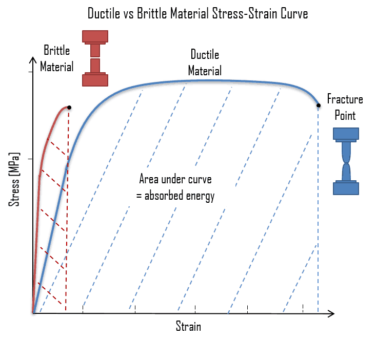
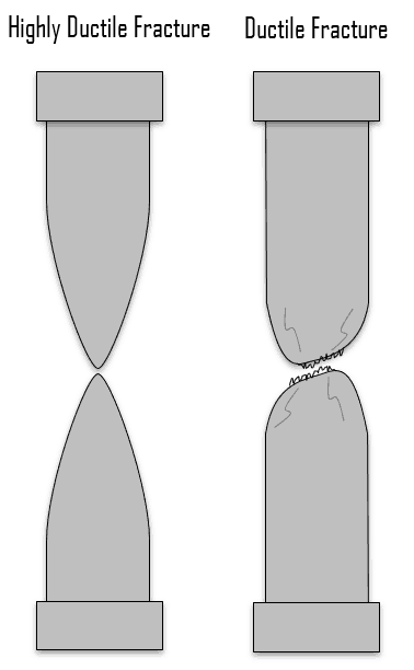
Ductile materials show large deformation before fracture. Ductile fracture (shear fracture) is better than brittle fracture, because there is slow propagation and an absorption of a large amount energy before fracture.

Stress-strain curves - Ductile vs Brittle MaterialToughness can also be defined with respect to regions of a stress–strain diagram (for low-strain rate). Toughness is related to the area under the stress–strain curve. The stress-strain curve measures toughness under gradually increasing load. Tensile toughness is measured in units of joule per cubic metre (J·m−3) in the SI system. In order to be tough, a material must be both strong and ductile. The following figure shows a typical stress-strain curve of a ductile material and a brittle material. For example, brittle materials (like ceramics) that are strong but with limited ductility are not tough; conversely, very ductile materials with low strengths are also not tough. To be tough, a material should withstand both high stresses and high strains.

Ductile Fracture

A fracture is the separation of an object or material into two or more pieces under the action of stress. Engineers need to understand fracture mechanisms. There are fractures (e.g. brittle fracture), which occur under specific conditions without warning and can cause major damage to materials. Brittle fracture occurs suddenly and catastrophically without any warning. This is a consequence of the spontaneous and rapid crack propagation. However, for ductile fracture, the presence of plastic deformation gives warning that failure is imminent, allowing preventive measures to be taken. A detailed understanding of how fracture occurs in materials may be assisted by the study of fracture mechanics.

In the tensile test, the fracture point is the point of strain where the material physically separates. At this point, the strain reaches its maximum value and the material actually fractures, even though the corresponding stress may be less than the ultimate strength at this point. Ductile materials have a fracture strength lower than the ultimate tensile strength (UTS), whereas in brittle materials the fracture strength is equivalent to the UTS. If a ductile material reaches its ultimate tensile strength in a load-controlled situation, it will continue to deform, with no additional load application, until it ruptures. However, if the loading is displacement-controlled, the deformation of the material may relieve the load, preventing rupture. It is possible to distinguish some common characteristics among the stress–strain curves of various groups of materials. On this basis, it is possible to divide materials into two broad categories; namely:

  • ductile fractureDuctile Materials. Ductility is the ability of a material to be elongated in tension. Ductile material will deform (elongate) more than brittle material. Ductile materials show large deformation before fracture. In ductile fracture, extensive plastic deformation (necking) takes place before fracture. Ductile fracture (shear fracture) is better than brittle fracture, because there is slow propagation and an absorption of a large amount energy before fracture. Any fracture process involves two steps, crack formation and propagation, in response to an imposed stress. The mode of fracture is highly dependent on the mechanism of crack propagation. Cracks in ductile materials are said to be stable (i.e., resist extension without an increase in applied stress). For brittle materials, cracks are unstable. That means crack propagation, once started, continues spontaneously without an increase in stress level. Ductility is desirable in the high temperature and high pressure applications in reactor plants because of the added stresses on the metals. High ductility in these applications helps prevent brittle fracture.
  • Brittle Materials. Brittle materials, when subjected to stress, break with little elastic deformation and without significant plastic deformation. Brittle materials absorb relatively little energy prior to fracture, even those of high strength. In brittle fracture (transgranular cleavage), no apparent plastic deformation takes place before fracture. In crystalography, cleavage is the tendency of crystalline materials to split along definite crystallographic structural planes. Any fracture process involves two steps, crack formation and propagation, in response to an imposed stress. The mode of fracture is highly dependent on the mechanism of crack propagation. For brittle materials, cracks are unstable. That means crack propagation, once started, continues spontaneously without an increase in stress level. Cracks propagate rapidly (speed of sound) and occurs at high speeds – up to 2133.6 m/s in steel. It should be noted that smaller grain size, higher temperature, and lower stress tend to mitigate crack initiation. Larger grain size, lower temperatures, and higher stress tend to favor crack propagation. There is a stress level below which a crack will not propagate at any temperature. This is called the lower fracture propagation stress. For brittle fracture, the fracture surface is relatively flat and perpendicular to the direction of the applied tensile load. In general, brittle fracture requires three conditions:
    • Flaw such as a crack
    • Stress sufficient to develop a small deformation at the crack tip
    • Temperature at or below DBTT

See also: Ductile-brittle Transition Temperature

See also: Stress-corrosion Cracking

See also: Hydrogen Embrittlement

References:
Materials Science:
  1. U.S. Department of Energy, Material Science. DOE Fundamentals Handbook, Volume 1 and 2. January 1993.
  2. U.S. Department of Energy, Material Science. DOE Fundamentals Handbook, Volume 2 and 2. January 1993.
  3. William D. Callister, David G. Rethwisch. Materials Science and Engineering: An Introduction 9th Edition, Wiley; 9 edition (December 4, 2013), ISBN-13: 978-1118324578.
  4. Eberhart, Mark (2003). Why Things Break: Understanding the World by the Way It Comes Apart. Harmony. ISBN 978-1-4000-4760-4.
  5. Gaskell, David R. (1995). Introduction to the thermodynamics of Materials (4th ed.). Taylor and Francis Publishing. ISBN 978-1-56032-992-3.
  6. González-Viñas, W. & Mancini, H.L. (2004). An Introduction to Materials Science. Princeton University Press. ISBN 978-0-691-07097-1.
  7. Ashby, Michael; Hugh Shercliff; David Cebon (2007). Materials: engineering, science, processing and design (1st ed.). Butterworth-Heinemann. ISBN 978-0-7506-8391-3.
  8. J. R. Lamarsh, A. J. Baratta, Introduction to Nuclear Engineering, 3d ed., Prentice-Hall, 2001, ISBN: 0-201-82498-1.

See above:

Toughness

We hope, this article, Ductile Material – Ductile Fracture, helps you. If so, give us a like in the sidebar. Main purpose of this website is to help the public to learn some interesting and important information about materials and their properties.
What is Brittle Material – Brittle Fracture – Definition

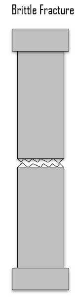
Brittle materials absorb relatively little energy prior to fracture, even those of high strength. In brittle fracture (transgranular cleavage), no apparent plastic deformation takes place before fracture.

Stress-strain curves - Ductile vs Brittle MaterialToughness can also be defined with respect to regions of a stress–strain diagram (for low-strain rate). Toughness is related to the area under the stress–strain curve. The stress-strain curve measures toughness under gradually increasing load. Tensile toughness is measured in units of joule per cubic metre (J·m−3) in the SI system. In order to be tough, a material must be both strong and ductile. The following figure shows a typical stress-strain curve of a ductile material and a brittle material. For example, brittle materials (like ceramics) that are strong but with limited ductility are not tough; conversely, very ductile materials with low strengths are also not tough. To be tough, a material should withstand both high stresses and high strains.

Ductile Fracture

A fracture is the separation of an object or material into two or more pieces under the action of stress. Engineers need to understand fracture mechanisms. There are fractures (e.g. brittle fracture), which occur under specific conditions without warning and can cause major damage to materials. Brittle fracture occurs suddenly and catastrophically without any warning. This is a consequence of the spontaneous and rapid crack propagation. However, for ductile fracture, the presence of plastic deformation gives warning that failure is imminent, allowing preventive measures to be taken. A detailed understanding of how fracture occurs in materials may be assisted by the study of fracture mechanics.

In the tensile test, the fracture point is the point of strain where the material physically separates. At this point, the strain reaches its maximum value and the material actually fractures, even though the corresponding stress may be less than the ultimate strength at this point. Ductile materials have a fracture strength lower than the ultimate tensile strength (UTS), whereas in brittle materials the fracture strength is equivalent to the UTS. If a ductile material reaches its ultimate tensile strength in a load-controlled situation, it will continue to deform, with no additional load application, until it ruptures. However, if the loading is displacement-controlled, the deformation of the material may relieve the load, preventing rupture. It is possible to distinguish some common characteristics among the stress–strain curves of various groups of materials. On this basis, it is possible to divide materials into two broad categories; namely:

  • Ductile Materials. Ductility is the ability of a material to be elongated in tension. Ductile material will deform (elongate) more than brittle material. Ductile materials show large deformation before fracture. In ductile fracture, extensive plastic deformation (necking) takes place before fracture. Ductile fracture (shear fracture) is better than brittle fracture, because there is slow propagation and an absorption of a large amount energy before fracture. Any fracture process involves two steps, crack formation and propagation, in response to an imposed stress. The mode of fracture is highly dependent on the mechanism of crack propagation. Cracks in ductile materials are said to be stable (i.e., resist extension without an increase in applied stress). For brittle materials, cracks are unstable. That means crack propagation, once started, continues spontaneously without an increase in stress level. Ductility is desirable in the high temperature and high pressure applications in reactor plants because of the added stresses on the metals. High ductility in these applications helps prevent brittle fracture.
  • brittle fractureBrittle Materials. Brittle materials, when subjected to stress, break with little elastic deformation and without significant plastic deformation. Brittle materials absorb relatively little energy prior to fracture, even those of high strength. In brittle fracture (transgranular cleavage), no apparent plastic deformation takes place before fracture. In crystalography, cleavage is the tendency of crystalline materials to split along definite crystallographic structural planes. Any fracture process involves two steps, crack formation and propagation, in response to an imposed stress. The mode of fracture is highly dependent on the mechanism of crack propagation. For brittle materials, cracks are unstable. That means crack propagation, once started, continues spontaneously without an increase in stress level. Cracks propagate rapidly (speed of sound) and occurs at high speeds – up to 2133.6 m/s in steel. It should be noted that smaller grain size, higher temperature, and lower stress tend to mitigate crack initiation. Larger grain size, lower temperatures, and higher stress tend to favor crack propagation. There is a stress level below which a crack will not propagate at any temperature. This is called the lower fracture propagation stress. For brittle fracture, the fracture surface is relatively flat and perpendicular to the direction of the applied tensile load. In general, brittle fracture requires three conditions:
    • Flaw such as a crack
    • Stress sufficient to develop a small deformation at the crack tip
    • Temperature at or below DBTT

See also: Ductile-brittle Transition Temperature

See also: Stress-corrosion Cracking

See also: Hydrogen Embrittlement

References:
Materials Science:
  1. U.S. Department of Energy, Material Science. DOE Fundamentals Handbook, Volume 1 and 2. January 1993.
  2. U.S. Department of Energy, Material Science. DOE Fundamentals Handbook, Volume 2 and 2. January 1993.
  3. William D. Callister, David G. Rethwisch. Materials Science and Engineering: An Introduction 9th Edition, Wiley; 9 edition (December 4, 2013), ISBN-13: 978-1118324578.
  4. Eberhart, Mark (2003). Why Things Break: Understanding the World by the Way It Comes Apart. Harmony. ISBN 978-1-4000-4760-4.
  5. Gaskell, David R. (1995). Introduction to the thermodynamics of Materials (4th ed.). Taylor and Francis Publishing. ISBN 978-1-56032-992-3.
  6. González-Viñas, W. & Mancini, H.L. (2004). An Introduction to Materials Science. Princeton University Press. ISBN 978-0-691-07097-1.
  7. Ashby, Michael; Hugh Shercliff; David Cebon (2007). Materials: engineering, science, processing and design (1st ed.). Butterworth-Heinemann. ISBN 978-0-7506-8391-3.
  8. J. R. Lamarsh, A. J. Baratta, Introduction to Nuclear Engineering, 3d ed., Prentice-Hall, 2001, ISBN: 0-201-82498-1.

See above:

Toughness

We hope, this article, Brittle Material – Brittle Fracture, helps you. If so, give us a like in the sidebar. Main purpose of this website is to help the public to learn some interesting and important information about materials and their properties.
What is Izod Impact Test – Definition

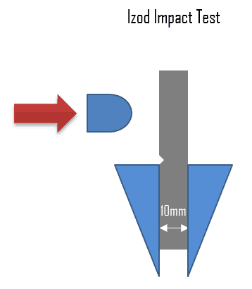
The Izod impact test differs from the Charpy impact test in that the sample is held in a cantilevered beam configuration as opposed to a three-point bending configuration.

Charpy testAs was written, toughness can be measured by the Charpy test or the Izod test. These two standardized impact tests, the Charpy and the Izod, are used to measure the impact energy (sometimes also termed notch toughness). The Charpy V-notch (CVN) technique is most commonly used. Both of these tests use a notched sample of defined cross-section. For these dynamic loading conditions and when a notch is present, we are using notch toughness. The location and shape of the notch are standard. The points of support of the sample, as well as the impact of the hammer, must bear a constant relationship to the location of the notch.

The tests are conducted by mounting the samples as shown in the figure and allowing a pendulum of a known weight to fall from a set height. The height from which the pendulum fell, minus the height to which it rose after deforming the specimen, multiplied by the weight of the pendulum is a measure of the energy absorbed by the specimen as it was deformed during the impact with the pendulum. The greater the amount of energy absorbed by the specimen, the smaller the upward swing of the pendulum will be and the tougher the material is. Indication of toughness is relative and applicable only to cases involving exactly this type of sample and method of loading.

A sample of a different shape will yield an entirely different result. Notches confine the deformation to a small volume of metal that reduces toughness. The Izod impact test is similar to the Charpy impact test but uses a different arrangement of the specimen under test. The Izod impact test differs from the Charpy impact test in that the sample is held in a cantilevered beam configuration as opposed to a three-point bending configuration.

Notch toughness is measure of the energy absorbed (impact energy) during the fracture of a specimen (in the presence of a flaw – usually a V-notch) of standard dimensions and geometry when subjected to very rapid (impact) loading. As mentioned previously, in the presence of a flaw, such as a notch or crack, a material will likely exhibit a lower level of toughness. Charpy and Izod impact tests are used to measure this parameter, which is important in assessing the ductile-to-brittle transition behavior of a material. Similarly as for tensile toughness, notch toughness is measured in units of joule per cubic metre (J·m−3) in the SI system, but in this case we are measuring the area at the notch position.

References:
Materials Science:
  1. U.S. Department of Energy, Material Science. DOE Fundamentals Handbook, Volume 1 and 2. January 1993.
  2. U.S. Department of Energy, Material Science. DOE Fundamentals Handbook, Volume 2 and 2. January 1993.
  3. William D. Callister, David G. Rethwisch. Materials Science and Engineering: An Introduction 9th Edition, Wiley; 9 edition (December 4, 2013), ISBN-13: 978-1118324578.
  4. Eberhart, Mark (2003). Why Things Break: Understanding the World by the Way It Comes Apart. Harmony. ISBN 978-1-4000-4760-4.
  5. Gaskell, David R. (1995). Introduction to the thermodynamics of Materials (4th ed.). Taylor and Francis Publishing. ISBN 978-1-56032-992-3.
  6. González-Viñas, W. & Mancini, H.L. (2004). An Introduction to Materials Science. Princeton University Press. ISBN 978-0-691-07097-1.
  7. Ashby, Michael; Hugh Shercliff; David Cebon (2007). Materials: engineering, science, processing and design (1st ed.). Butterworth-Heinemann. ISBN 978-0-7506-8391-3.
  8. J. R. Lamarsh, A. J. Baratta, Introduction to Nuclear Engineering, 3d ed., Prentice-Hall, 2001, ISBN: 0-201-82498-1.

See above:

Toughness

We hope, this article, Izod Impact Test, helps you. If so, give us a like in the sidebar. Main purpose of this website is to help the public to learn some interesting and important information about materials and their properties.
What is Fracture of Material – Fracture Mechanics – Definition

A fracture is the separation of an object or material into two or more pieces under the action of stress. Engineers need to understand fracture mechanisms.

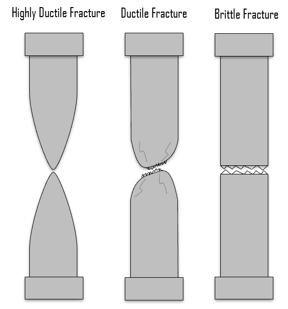
fractureA fracture is the separation of an object or material into two or more pieces under the action of stress. Engineers need to understand fracture mechanisms. There are fractures (e.g. brittle fracture), which occur under specific conditions without warning and can cause major damage to materials. Brittle fracture occurs suddenly and catastrophically without any warning. This is a consequence of the spontaneous and rapid crack propagation. However, for ductile fracture, the presence of plastic deformation gives warning that failure is imminent, allowing preventive measures to be taken. A detailed understanding of how fracture occurs in materials may be assisted by the study of fracture mechanics.

In the tensile test, the fracture point is the point of strain where the material physically separates. At this point, the strain reaches its maximum value and the material actually fractures, even though the corresponding stress may be less than the ultimate strength at this point. Ductile materials have a fracture strength lower than the ultimate tensile strength (UTS), whereas in brittle materials the fracture strength is equivalent to the UTS. If a ductile material reaches its ultimate tensile strength in a load-controlled situation, it will continue to deform, with no additional load application, until it ruptures. However, if the loading is displacement-controlled, the deformation of the material may relieve the load, preventing rupture. It is possible to distinguish some common characteristics among the stress–strain curves of various groups of materials. On this basis, it is possible to divide materials into two broad categories; namely:

  • Ductile Materials. Ductility is the ability of a material to be elongated in tension. Ductile material will deform (elongate) more than brittle material. Ductile materials show large deformation before fracture. In ductile fracture, extensive plastic deformation (necking) takes place before fracture. Ductile fracture (shear fracture) is better than brittle fracture, because there is slow propagation and an absorption of a large amount energy before fracture. Any fracture process involves two steps, crack formation and propagation, in response to an imposed stress. The mode of fracture is highly dependent on the mechanism of crack propagation. Cracks in ductile materials are said to be stable (i.e., resist extension without an increase in applied stress). For brittle materials, cracks are unstable. That means crack propagation, once started, continues spontaneously without an increase in stress level. Ductility is desirable in the high temperature and high pressure applications in reactor plants because of the added stresses on the metals. High ductility in these applications helps prevent brittle fracture.
  • Brittle Materials. Brittle materials, when subjected to stress, break with little elastic deformation and without significant plastic deformation. Brittle materials absorb relatively little energy prior to fracture, even those of high strength. In brittle fracture (transgranular cleavage), no apparent plastic deformation takes place before fracture. In crystalography, cleavage is the tendency of crystalline materials to split along definite crystallographic structural planes. Any fracture process involves two steps, crack formation and propagation, in response to an imposed stress. The mode of fracture is highly dependent on the mechanism of crack propagation. For brittle materials, cracks are unstable. That means crack propagation, once started, continues spontaneously without an increase in stress level. Cracks propagate rapidly (speed of sound) and occurs at high speeds – up to 2133.6 m/s in steel. It should be noted that smaller grain size, higher temperature, and lower stress tend to mitigate crack initiation. Larger grain size, lower temperatures, and higher stress tend to favor crack propagation. There is a stress level below which a crack will not propagate at any temperature. This is called the lower fracture propagation stress. For brittle fracture, the fracture surface is relatively flat and perpendicular to the direction of the applied tensile load. In general, brittle fracture requires three conditions:
    • Flaw such as a crack
    • Stress sufficient to develop a small deformation at the crack tip
    • Temperature at or below DBTT

See also: Ductile-brittle Transition Temperature

See also: Stress-corrosion Cracking

See also: Hydrogen Embrittlement

References:
Materials Science:
  1. U.S. Department of Energy, Material Science. DOE Fundamentals Handbook, Volume 1 and 2. January 1993.
  2. U.S. Department of Energy, Material Science. DOE Fundamentals Handbook, Volume 2 and 2. January 1993.
  3. William D. Callister, David G. Rethwisch. Materials Science and Engineering: An Introduction 9th Edition, Wiley; 9 edition (December 4, 2013), ISBN-13: 978-1118324578.
  4. Eberhart, Mark (2003). Why Things Break: Understanding the World by the Way It Comes Apart. Harmony. ISBN 978-1-4000-4760-4.
  5. Gaskell, David R. (1995). Introduction to the thermodynamics of Materials (4th ed.). Taylor and Francis Publishing. ISBN 978-1-56032-992-3.
  6. González-Viñas, W. & Mancini, H.L. (2004). An Introduction to Materials Science. Princeton University Press. ISBN 978-0-691-07097-1.
  7. Ashby, Michael; Hugh Shercliff; David Cebon (2007). Materials: engineering, science, processing and design (1st ed.). Butterworth-Heinemann. ISBN 978-0-7506-8391-3.
  8. J. R. Lamarsh, A. J. Baratta, Introduction to Nuclear Engineering, 3d ed., Prentice-Hall, 2001, ISBN: 0-201-82498-1.

See above:

Toughness

We hope, this article, Fracture of Material – Fracture Mechanics, helps you. If so, give us a like in the sidebar. Main purpose of this website is to help the public to learn some interesting and important information about materials and their properties.

Measuring Toughness – Impact Tests – Definition

Toughness can be measured by the Charpy test or the Izod test. These two standardized impact tests, the Charpy and the Izod, are used to measure the impact energy (sometimes also termed notch toughness).

Charpy testAs was written, toughness can be measured by the Charpy test or the Izod test. These two standardized impact tests, the Charpy and the Izod, are used to measure the impact energy (sometimes also termed notch toughness). The Charpy V-notch (CVN) technique is most commonly used. Both of these tests use a notched sample of defined cross-section. For these dynamic loading conditions and when a notch is present, we are using notch toughness. The location and shape of the notch are standard. The points of support of the sample, as well as the impact of the hammer, must bear a constant relationship to the location of the notch.

Charpy testThe tests are conducted by mounting the samples as shown in the figure and allowing a pendulum of a known weight to fall from a set height. The height from which the pendulum fell, minus the height to which it rose after deforming the specimen, multiplied by the weight of the pendulum is a measure of the energy absorbed by the specimen as it was deformed during the impact with the pendulum. The greater the amount of energy absorbed by the specimen, the smaller the upward swing of the pendulum will be and the tougher the material is.

Indication of toughness is relative and applicable only to cases involving exactly this type of sample and method of loading.

charpy impact test
Charpy Impact Test. Source: U.S. Department of Energy, Material Science. DOE Fundamentals Handbook, Volume 1 and 2. January 1993.

A sample of a different shape will yield an entirely different result. Notches confine the deformation to a small volume of metal that reduces toughness. The Izod impact test is similar to the Charpy impact test but uses a different arrangement of the specimen under test. The Izod impact test differs from the Charpy impact test in that the sample is held in a cantilevered beam configuration as opposed to a three-point bending configuration.


References:
Materials Science:
  1. U.S. Department of Energy, Material Science. DOE Fundamentals Handbook, Volume 1 and 2. January 1993.
  2. U.S. Department of Energy, Material Science. DOE Fundamentals Handbook, Volume 2 and 2. January 1993.
  3. William D. Callister, David G. Rethwisch. Materials Science and Engineering: An Introduction 9th Edition, Wiley; 9 edition (December 4, 2013), ISBN-13: 978-1118324578.
  4. Eberhart, Mark (2003). Why Things Break: Understanding the World by the Way It Comes Apart. Harmony. ISBN 978-1-4000-4760-4.
  5. Gaskell, David R. (1995). Introduction to the thermodynamics of Materials (4th ed.). Taylor and Francis Publishing. ISBN 978-1-56032-992-3.
  6. González-Viñas, W. & Mancini, H.L. (2004). An Introduction to Materials Science. Princeton University Press. ISBN 978-0-691-07097-1.
  7. Ashby, Michael; Hugh Shercliff; David Cebon (2007). Materials: engineering, science, processing and design (1st ed.). Butterworth-Heinemann. ISBN 978-0-7506-8391-3.
  8. J. R. Lamarsh, A. J. Baratta, Introduction to Nuclear Engineering, 3d ed., Prentice-Hall, 2001, ISBN: 0-201-82498-1.

See above:

Toughness

We hope, this article, Measuring Toughness – Impact Tests, helps you. If so, give us a like in the sidebar. Main purpose of this website is to help the public to learn some interesting and important information about materials and their properties.
What is Charpy Impact Test – Definition

The Charpy impact test, especially the Charpy V-notch (CVN) technique is one of most commonly used toughness tests. Charpy Impact Test

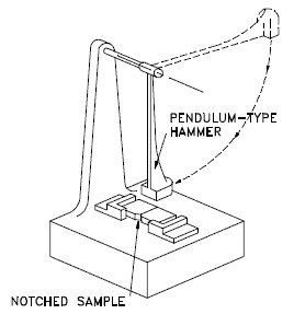
Charpy testAs was written, toughness can be measured by the Charpy test or the Izod test. These two standardized impact tests, the Charpy and the Izod, are used to measure the impact energy (sometimes also termed notch toughness). The Charpy V-notch (CVN) technique is most commonly used. Both of these tests use a notched sample of defined cross-section. For these dynamic loading conditions and when a notch is present, we are using notch toughness. The location and shape of the notch are standard. The points of support of the sample, as well as the impact of the hammer, must bear a constant relationship to the location of the notch.

The tests are conducted by mounting the samples as shown in the figure and allowing a pendulum of a known weight to fall from a set height. The height from which the pendulum fell, minus the height to which it rose after deforming the specimen, multiplied by the weight of the pendulum is a measure of the energy absorbed by the specimen as it was deformed during the impact with the pendulum. The greater the amount of energy absorbed by the specimen, the smaller the upward swing of the pendulum will be and the tougher the material is. Indication of toughness is relative and applicable only to cases involving exactly this type of sample and method of loading.

charpy impact test
Charpy Impact Test. Source: U.S. Department of Energy, Material Science. DOE Fundamentals Handbook, Volume 1 and 2. January 1993.

A sample of a different shape will yield an entirely different result. Notches confine the deformation to a small volume of metal that reduces toughness. The Izod impact test is similar to the Charpy impact test but uses a different arrangement of the specimen under test. The Izod impact test differs from the Charpy impact test in that the sample is held in a cantilevered beam configuration as opposed to a three-point bending configuration.

Notch toughness is measure of the energy absorbed (impact energy) during the fracture of a specimen (in the presence of a flaw – usually a V-notch) of standard dimensions and geometry when subjected to very rapid (impact) loading. As mentioned previously, in the presence of a flaw, such as a notch or crack, a material will likely exhibit a lower level of toughness. Charpy and Izod impact tests are used to measure this parameter, which is important in assessing the ductile-to-brittle transition behavior of a material. Similarly as for tensile toughness, notch toughness is measured in units of joule per cubic metre (J·m−3) in the SI system, but in this case we are measuring the area at the notch position.

References:
Materials Science:
  1. U.S. Department of Energy, Material Science. DOE Fundamentals Handbook, Volume 1 and 2. January 1993.
  2. U.S. Department of Energy, Material Science. DOE Fundamentals Handbook, Volume 2 and 2. January 1993.
  3. William D. Callister, David G. Rethwisch. Materials Science and Engineering: An Introduction 9th Edition, Wiley; 9 edition (December 4, 2013), ISBN-13: 978-1118324578.
  4. Eberhart, Mark (2003). Why Things Break: Understanding the World by the Way It Comes Apart. Harmony. ISBN 978-1-4000-4760-4.
  5. Gaskell, David R. (1995). Introduction to the thermodynamics of Materials (4th ed.). Taylor and Francis Publishing. ISBN 978-1-56032-992-3.
  6. González-Viñas, W. & Mancini, H.L. (2004). An Introduction to Materials Science. Princeton University Press. ISBN 978-0-691-07097-1.
  7. Ashby, Michael; Hugh Shercliff; David Cebon (2007). Materials: engineering, science, processing and design (1st ed.). Butterworth-Heinemann. ISBN 978-0-7506-8391-3.
  8. J. R. Lamarsh, A. J. Baratta, Introduction to Nuclear Engineering, 3d ed., Prentice-Hall, 2001, ISBN: 0-201-82498-1.

See above:

Toughness

We hope, this article, Charpy Impact Test, helps you. If so, give us a like in the sidebar. Main purpose of this website is to help the public to learn some interesting and important information about materials and their properties.

What is Unit of Toughness – Definition

Tensile toughness is measured in units of joule per cubic metre (J·m−3) in the SI system. Similarly as for tensile toughness, notch toughness is measured in units of joule per cubic metre (J·m−3). Unit of Toughness

Stress-strain curves - Ductile vs Brittle MaterialToughness can be defined with respect to regions of a stress–strain diagram (for low-strain rate). Toughness is related to the area under the stress–strain curve. The stress-strain curve measures toughness under gradually increasing load. Tensile toughness is measured in units of joule per cubic metre (J·m−3) in the SI system. In order to be tough, a material must be both strong and ductile. The following figure shows a typical stress-strain curve of a ductile material and a brittle material. For example, brittle materials (like ceramics) that are strong but with limited ductility are not tough; conversely, very ductile materials with low strengths are also not tough. To be tough, a material should withstand both high stresses and high strains.

Notch Toughness

Charpy testNotch toughness is measure of the energy absorbed (impact energy) during the fracture of a specimen (in the presence of a flaw – usually a V-notch) of standard dimensions and geometry when subjected to very rapid (impact) loading. As mentioned previously, in the presence of a flaw, such as a notch or crack, a material will likely exhibit a lower level of toughness. Charpy and Izod impact tests are used to measure this parameter, which is important in assessing the ductile-to-brittle transition behavior of a material. Similarly as for tensile toughness, notch toughness is measured in units of joule per cubic metre (J·m−3) in the SI system, but in this case we are measuring the area at the notch position.

References:
Materials Science:
  1. U.S. Department of Energy, Material Science. DOE Fundamentals Handbook, Volume 1 and 2. January 1993.
  2. U.S. Department of Energy, Material Science. DOE Fundamentals Handbook, Volume 2 and 2. January 1993.
  3. William D. Callister, David G. Rethwisch. Materials Science and Engineering: An Introduction 9th Edition, Wiley; 9 edition (December 4, 2013), ISBN-13: 978-1118324578.
  4. Eberhart, Mark (2003). Why Things Break: Understanding the World by the Way It Comes Apart. Harmony. ISBN 978-1-4000-4760-4.
  5. Gaskell, David R. (1995). Introduction to the thermodynamics of Materials (4th ed.). Taylor and Francis Publishing. ISBN 978-1-56032-992-3.
  6. González-Viñas, W. & Mancini, H.L. (2004). An Introduction to Materials Science. Princeton University Press. ISBN 978-0-691-07097-1.
  7. Ashby, Michael; Hugh Shercliff; David Cebon (2007). Materials: engineering, science, processing and design (1st ed.). Butterworth-Heinemann. ISBN 978-0-7506-8391-3.
  8. J. R. Lamarsh, A. J. Baratta, Introduction to Nuclear Engineering, 3d ed., Prentice-Hall, 2001, ISBN: 0-201-82498-1.

See above:

Toughness

We hope, this article, Unit of Toughness, helps you. If so, give us a like in the sidebar. Main purpose of this website is to help the public to learn some interesting and important information about materials and their properties.

What is Notch Toughness – Definition

Notch toughness is measure of the energy absorbed (impact energy) during the fracture of a specimen (in the presence of a flaw – usually a V-notch).

Notch toughness is measure of the energy absorbed (impact energy) during the fracture of a specimen (in the presence of a flaw – usually a V-notch) of standard dimensions and geometry when subjected to very rapid (impact) loading. As mentioned previously, in the presence of a flaw, such as a notch or crack, a material will likely exhibit a lower level of toughness. Charpy and Izod impact tests are used to measure this parameter, which is important in assessing the ductile-to-brittle transition behavior of a material. Similarly as for tensile toughness, notch toughness is measured in units of joule per cubic metre (J·m−3) in the SI system, but in this case we are measuring the area at the notch position.

Measuring Toughness – Impact Tests

Charpy testAs was written, toughness can be measured by the Charpy test or the Izod test. These two standardized impact tests, the Charpy and the Izod, are used to measure the impact energy (sometimes also termed notch toughness). The Charpy V-notch (CVN) technique is most commonly used. Both of these tests use a notched sample of defined cross-section. For these dynamic loading conditions and when a notch is present, we are using notch toughness. The location and shape of the notch are standard. The points of support of the sample, as well as the impact of the hammer, must bear a constant relationship to the location of the notch.

Charpy testThe tests are conducted by mounting the samples as shown in the figure and allowing a pendulum of a known weight to fall from a set height. The height from which the pendulum fell, minus the height to which it rose after deforming the specimen, multiplied by the weight of the pendulum is a measure of the energy absorbed by the specimen as it was deformed during the impact with the pendulum. The greater the amount of energy absorbed by the specimen, the smaller the upward swing of the pendulum will be and the tougher the material is.

Indication of toughness is relative and applicable only to cases involving exactly this type of sample and method of loading.

charpy impact test
Charpy Impact Test. Source: U.S. Department of Energy, Material Science. DOE Fundamentals Handbook, Volume 1 and 2. January 1993.

A sample of a different shape will yield an entirely different result. Notches confine the deformation to a small volume of metal that reduces toughness. The Izod impact test is similar to the Charpy impact test but uses a different arrangement of the specimen under test. The Izod impact test differs from the Charpy impact test in that the sample is held in a cantilevered beam configuration as opposed to a three-point bending configuration.


References:
Materials Science:
  1. U.S. Department of Energy, Material Science. DOE Fundamentals Handbook, Volume 1 and 2. January 1993.
  2. U.S. Department of Energy, Material Science. DOE Fundamentals Handbook, Volume 2 and 2. January 1993.
  3. William D. Callister, David G. Rethwisch. Materials Science and Engineering: An Introduction 9th Edition, Wiley; 9 edition (December 4, 2013), ISBN-13: 978-1118324578.
  4. Eberhart, Mark (2003). Why Things Break: Understanding the World by the Way It Comes Apart. Harmony. ISBN 978-1-4000-4760-4.
  5. Gaskell, David R. (1995). Introduction to the thermodynamics of Materials (4th ed.). Taylor and Francis Publishing. ISBN 978-1-56032-992-3.
  6. González-Viñas, W. & Mancini, H.L. (2004). An Introduction to Materials Science. Princeton University Press. ISBN 978-0-691-07097-1.
  7. Ashby, Michael; Hugh Shercliff; David Cebon (2007). Materials: engineering, science, processing and design (1st ed.). Butterworth-Heinemann. ISBN 978-0-7506-8391-3.
  8. J. R. Lamarsh, A. J. Baratta, Introduction to Nuclear Engineering, 3d ed., Prentice-Hall, 2001, ISBN: 0-201-82498-1.

See above:

Toughness

We hope, this article, Notch Toughness, helps you. If so, give us a like in the sidebar. Main purpose of this website is to help the public to learn some interesting and important information about materials and their properties.

What is Malleability – Definition

In materials science, malleability is the ability of a material to undergo large plastic deformations under compressive stress. Malleable materials can be flattened into metal leaf.

In materials science, malleability is the ability of a material to undergo large plastic deformations under compressive stress. Compressive stress is the reverse of tensile stress. Adjacent parts of the material tend to press against each other through a typical stress plane. If malleable, a material may be flattened into thin sheets by hammering or rolling. Malleable materials can be flattened into metal leaf. Many metals with high malleability also have high ductility.

Gold is the most malleable of all metals. Gold is a bright, slightly reddish yellow, dense, soft, malleable, and ductile metal. It can be drawn into a monoatomic wire, and then stretched about twice before it breaks. Such nanowires distort via formation, reorientation and migration of dislocations and crystal twins without noticeable hardening. A single gram of gold can be hammered into a gold foil of 1 square meter.

References:
Materials Science:
  1. U.S. Department of Energy, Material Science. DOE Fundamentals Handbook, Volume 1 and 2. January 1993.
  2. U.S. Department of Energy, Material Science. DOE Fundamentals Handbook, Volume 2 and 2. January 1993.
  3. William D. Callister, David G. Rethwisch. Materials Science and Engineering: An Introduction 9th Edition, Wiley; 9 edition (December 4, 2013), ISBN-13: 978-1118324578.
  4. Eberhart, Mark (2003). Why Things Break: Understanding the World by the Way It Comes Apart. Harmony. ISBN 978-1-4000-4760-4.
  5. Gaskell, David R. (1995). Introduction to the thermodynamics of Materials (4th ed.). Taylor and Francis Publishing. ISBN 978-1-56032-992-3.
  6. González-Viñas, W. & Mancini, H.L. (2004). An Introduction to Materials Science. Princeton University Press. ISBN 978-0-691-07097-1.
  7. Ashby, Michael; Hugh Shercliff; David Cebon (2007). Materials: engineering, science, processing and design (1st ed.). Butterworth-Heinemann. ISBN 978-0-7506-8391-3.
  8. J. R. Lamarsh, A. J. Baratta, Introduction to Nuclear Engineering, 3d ed., Prentice-Hall, 2001, ISBN: 0-201-82498-1.

See above:

Material Properties

We hope, this article, Malleability, helps you. If so, give us a like in the sidebar. Main purpose of this website is to help the public to learn some interesting and important information about materials and their properties.