Facebook Instagram Youtube Twitter

What are Wear Types – Classification and Differences – Definition

Wear is commonly classified according to so-called wear types, which occur in isolation or complex interaction. Wear mechanisms and/or sub-mechanisms frequently overlap and occur in a synergistic manner, producing a greater rate of wear than the sum of the individual wear mechanisms.

wearIn general, wear is mechanically induced surface damage that results in the progressive removal of material due to relative motion between that surface and a contacting substance or substances. A contacting substance may consist of another surface, a fluid, or hard, abrasive particles contained in some form of fluid or suspension, such as a lubricant for example. As is with friction, the presence of wear can be either good or bad. Productive, controlled wear can be found in processes like machining, cutting, grinding and polishing. However, in most of the technological applications, the occurrence of wear is highly undesirable and it is an enormously expensive problem since it leads to the deterioration or even failure of components. In terms of safety it is often not as serious (or as sudden) as fracture. This is because wear is usually anticipated.

Certain material characteristics such as hardness, carbide type, and volume percent can have a decided impact on the wear resistance of a material in a given application. Wear, like corrosion, has multiple types and subtypes, is predictable to some extent, and is rather difficult to reliably test and to evaluate in the lab or in service.

Wear Types

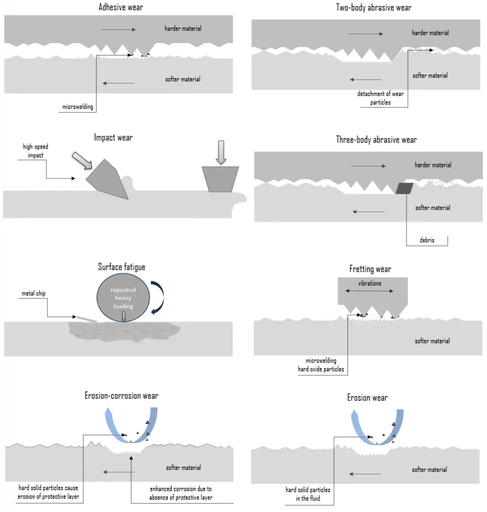
Wear is commonly classified according to so-called wear types, which occur in isolation or complex interaction. Wear mechanisms and/or sub-mechanisms frequently overlap and occur in a synergistic manner, producing a greater rate of wear than the sum of the individual wear mechanisms. The most common wear types are:

Other, less common types of wear are:

Abrasive Wear

Abrasive wear is defined as the loss of material due to hard particles or hard protuberances that are forced against and move along a solid surface. It occurs when a hard rough surface slides across a softer surface. This mechanism is sometimes referred to as grinding wear. The harder material may be one of the rubbing surfaces or hard particles that have found their way between the mating surfaces. These may be ‘foreign’ particles or particles resulting from adhesive or delamination wear. Abrasion mainly involves microscale cutting and plowing processes. The way an asperity slides over a surface determines the nature and intensity of abrasive wear. There are two basic modes of abrasive wear:

  • Two-body abrasive wear. Two-body wear occurs when the grits or hard particles remove material from the opposite surface. The common analogy is that of material being removed or displaced by a cutting or plowing operation.
  • Three-body abrasive wear. Three-body wear occurs when the particles are not constrained, and are free to roll and slide down a surface. The contact environment determines whether the wear is classified as open or closed. An open contact environment occurs when the surfaces are sufficiently displaced to be independent of one another.

There are a number of different strategies for mitigating abrasive wear, but the general rule for materials selection is, the harder the better. Materials that contain a relatively large percentage of hard, wear-resistant alloy carbides, such as selected tool steels and high-speed steels.

Adhesive Wear

Adhesive wear is originated through the bonding of asperities or microscopic high points (surface roughness) between two sliding materials. When a peak from one surface comes into contact with a peak from the other surface, instantaneous microwelding may take place due to the heat generated by the resulting friction. This results in detachment or material transfer from one surface to the other. For adhesive wear to occur it is necessary for the surfaces to be in intimate contact with each other. This may cause unwanted displacement and attachment of wear debris and material compounds from one surface to another. Adhesive wear can lead to an increase in roughness and the creation of protrusions (i.e., lumps) above the original surface. Surfaces which are held apart by lubricating films, oxide films etc. reduce the tendency for adhesion to occur. In some engineering applications, surfaces slide in air or without lubricant and the resulting wear is termed as dry sliding.

Adhesive wear is dependent on the materials involved, the degree of lubrication provided, and the environment. Adequate lubrication allows smooth, continuous operation of machine elements, reduces the rate of wear, and prevents excessive stresses or seizures at bearings. When lubrication breaks down, components can rub destructively against each other, causing heat, local welding, destructive damage and failure. For instance, austenitic stainless steels (e.g. AISI 304) sliding against themselves are very likely to transfer material and gall, resulting in severe surface damage. Other materials that are prone to adhesive wear include titanium, nickel, and zirconium. On the other hand, aluminium bronze has found increasing recognition for a wide variety of applications requiring resistance to mechanical wear. Its wear-resistance is based on the transfer from the softer metal (aluminium bronze) to the harder metal (steel) and formation of thin layer of softer metal on the harder metal.

For example, the main function of motor oil is to reduce friction and wear on moving parts (to reduce adhesive wear) and to clean the engine from sludge, while a filter is designed to remove contaminants and abrasive particles from engine oil.

Erosion Wear

Erosion wear is a process of progressive removal of material from a target surface due to repeated impacts of solid particles. The particles suspended in the flow of solid liquid mixture erode the wetted passes limiting the service life of equipment used for slurry transportation system. Each particle cuts or fractures a tiny amount of material (referred to as wear chips) from the surface. If this is repeated over a long period of time, a significant amount of material loss can result.

Erosive wear is common in pumps and impellers, fans, steam lines and nozzles, on the inside of sharp bends in tubes and pipes. Therefore, it is a widely encountered mechanism in industry and power engineering. Due to the nature of the conveying process, piping systems are prone to wear when abrasive particles have to be transported.

Erosion wear is caused by the kinetic energy transferred to target surface by impinging solid particles. The rate of erosive wear is dependent upon a number of factors. The material characteristics of the particles, such as their shape, hardness, impact velocity and impingement angle are primary factors along with the properties of the surface being eroded. Material loss of target material is higher for higher kinetic energy of impinging particle. So impact velocity largely affects the erosion wear of target material. The impingement angle is one of the most important factors and is widely recognized in literature. Sharp curves or bends tend to produce more erosion than gentle curves.

Erosion wear can be classified into three categories:

  • Solid particle erosion. Solid particle erosion is the loss of material volume from target material due to continues impingement of solid particles present in the flowing fluid.
  • Liquid impact erosion. The continues striking of liquid jet on material surface cause liquid impact erosion.
  • Cavitations erosion. When the vapor or gas in a liquid forms cavities or bubbles that cause wear.

In general, erosive wear resistance may be improved by increasing the hardness of the surface, by proper materials and proper design of the product. Some specific steps that can be taken to change flow conditions include: reducing fluid velocity, eliminating turbulence at misalignments and avoiding sharp bends.

Erosion – Corrosion

Erosion can also occur in combination with other forms of degradation, such as corrosion. This is referred to as erosion-corrosion. Erosion corrosion is a material degradation process due to the combined effect of corrosion and wear. Nearly all flowing or turbulent corrosive media can cause erosion corrosion. The mechanism can be described as follows:

  • mechanical erosion of the material, or protective (or passive) oxide layer on its surface,
  • enhanced corrosion of the material, if the corrosion rate of the material depends on the thickness of the oxide layer.

Wear is a mechanical material degradation process occurring on rubbing or impacting surfaces, while corrosion involves chemical or electrochemical reactions of the material. Corrosion may accelerate wear and wear may accelerate corrosion.

Fretting Wear

Fretting wear is a special wear process that occurs at the contact area between two materials under load and subject to minute relative motion by vibration or some other force. Fretting wear is similar to adhesive wear in that microwelding occurs on mating surfaces. In adhesive wear, however, facing metals slide across each other, while in fretting wear metal-to-metal interfaces are essentially stationary. The amplitude of the relative sliding motion is often in the order from micrometers to millimeters. Because fretting wear is essentially a stationary phenomenon, debris is retained at or near the locations where it was formed originally. This debris usually consists of oxides of the metals in contact. Because the oxidized debris is usually much harder than the surfaces from which it came, it often acts as an abrasive agent that increases the rate of fretting. Fretting wear occurs typically in bearings, although most bearings have their surfaces hardened to resist the problem.

 Fretting mitigation is based on following measures:

  • Reduce or eliminate vibration. The fundamental way to prevent fretting is to design for no relative motion of the surfaces at the contact
  • Use of an elastomeric material to prevent metal-to-metal contact.
  • Lubrication. The problem here is that because the joint is essentially stationary, liquid lubricant cannot flow through the in terface.

Debris Fretting – Grid-to-rod Fretting

In nuclear power plants, fuel cladding is the outer layer of the fuel rods, standing between the reactor coolant and the nuclear fuel (i.e. fuel pellets). It is made of a corrosion-resistant material with low absorption cross section for thermal neutrons (~ 0.18 × 10⁻²⁴ cm2), usually zirconium alloy. Cladding prevents radioactive fission products from escaping the fuel matrix into the reactor coolant and contaminating it. In the early dates of PWR and BWR operations, fretting was one of main failure mechanisms of this fuel cladding. It has typically two variants.

  • Debris fretting. Debris fretting can be caused by any debris (foregn material – usually metallic) that can enter the fuel bundle and that has the potential of becoming lodged between the spacer grid and a fuel rod. Fretting wear of fuel cladding can results in cladding penetration.
  • Grid-to-rod fretting. Grid-to-rod fretting arises from vibration of the fuel element generated by the high coolant velocity through the spacing grid. Spacing grids are welded onto the guide tubes and ensure, by means of springs and dimples, fuel rod support, and spacing. High coolant velocity can cause the rod to rub against the part of the spacer grid that holds it. This type of cladding wear can be minimized by proper design of the spacing grid. Baffle-jetting is usually grouped under grid-to-rod fretting.

See also: IAEA, Review of fuel failures in water cooled reactors. No. NF-T-2.1. ISBN 978–92–0–102610–1, Vienna, 2010.

Surface Fatigue – Fatigue Wear

In materials science, fatigue is the weakening of a material caused by cyclic loading that results in progressive, brittle and localized structural damage. Surface fatigue, or fatigue wear, is the cracking and subsequent pitting of surfaces subjected to alternating stresses during rolling contact or the stresses from combined rolling and sliding. Fatigue wear is produced when the wear particles are detached by cyclic crack growth of microcracks on the surface. These microcracks are either superficial cracks or subsurface cracks. The repeated loading and unloading cycles to which the materials are exposed may induce the formation of subsurface or surface cracks, which eventually, after a critical number of cycles, will result in the breakup of the surface with the formation of large fragments, leaving large pits in the surface. Once a crack has initiated, each loading cycle will grow the crack a small amount, even when repeated alternating or cyclic stresses are of an intensity considerably below the normal strength. The stresses could be due to vibration or thermal cycling. Subsurface and surface fatigues are observed during repeated rolling and sliding, respectively.

Corrosive and oxidation wear

Corrosive wear is a material degradation process due to the combined effect of corrosion and wear. It is defined as the wear process in which sliding takes place in a corrosive environment. In the absence of sliding, the products of the corrosion (e.g., oxides) would form a film typically less than a micrometer thick on the surfaces, which would tend to slow down or even eliminate the corrosion, but the sliding action wears the film away, so that further corrosion can continue. Oxidation wear is one of the most common forms of corrosive wear, because an oxygen-rich environment is a typical environment in which this wear process occurs. Corrosive wear requires both corrosion and rubbing. Chemical corrosion occurs in a highly corrosive environment and in high temperature and high humidity environments.

Erosion – Corrosion

Erosion can also occur in combination with other forms of degradation, such as corrosion. This is referred to as erosion-corrosion. Erosion corrosion is a material degradation process due to the combined effect of corrosion and wear. Nearly all flowing or turbulent corrosive media can cause erosion corrosion. The mechanism can be described as follows:

  • mechanical erosion of the material, or protective (or passive) oxide layer on its surface,
  • enhanced corrosion of the material, if the corrosion rate of the material depends on the thickness of the oxide layer.

Wear is a mechanical material degradation process occurring on rubbing or impacting surfaces, while corrosion involves chemical or electrochemical reactions of the material. Corrosion may accelerate wear and wear may accelerate corrosion.

Impact Wear

Impact wear is defined as the wear of a solid surface that is due to percussion, which is repetitive exposure to dynamic contact by another solid body. Impact wear is of the highest impostance in mining nad mineral processing. Mining and mineral processing demand wear-resistant machines and components, because the energies and masses of interacting bodies are significant. For this purposes, materials with the highest wear-resistance must be used. For example, tungsten carbide is used extensively in mining in top hammer rock drill bits, downhole hammers, roller-cutters, long wall plough chisels, long wall shearer picks, raiseboring reamers, and tunnel boring machines.

For metal impact pairs, the behavior of impact wear involves elastic and plastic deformation when impact loading or impact energy is high and/or fatigue accompanied by wear debris release due to crack formation. In general, impact wear of metals is dependent on the formation of deformed layers, particularly when wear by fatigue or crack formation is predominant. In such cases, subsurface cracks extend parallel to the surface in a manner very similar to delamination wear. Sufficient hardness of the impacted component is necessary to prevent rapid wear or extrusion of material from the contact by plastic deformation. In most situations this condition can be fulfilled by assuring an adequate hardness and then wear is controlled by other material characteristics.

Cavitation wear

Cavitation wear is a process of progressive degradation of material due to repeated nucleation, growth, and violent collapse of cavities in a liquid flowing near the material. Cavitation fatigue is a specific type of damage mechanism caused by repeated vibration and movement due to contact with flowing liquids, with water being the most common fluid. Cavitation is, in many cases, an undesirable occurrence. In centrifugal pumps, cavitation causes damage to components (erosion of the material), vibrations, noise and a loss of efficiency.
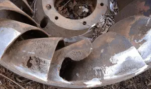
Source: Wikipedia, CC BY 2.5,
https://commons.wikimedia.org/wiki/File:Turbine_Francis_Worn.JPG

Perhaps the most important engineering problem caused by cavitation is the material damage that cavitation bubbles can cause when they collapse in the vicinity of a solid surface.  Cavitation bubbles collapse is a violent process that generates highly localized shock waves and microjets. They force energetic liquid into very small volumes, thereby creating spots of high temperature and these intense disturbances generate highly localized and transient surface stresses to a solid surface. Signs of erosion will appear as pitting due to the waterhammering action of the collapsing vapour bubbles. It has been found that cavitation damage rates increase rapidly with the increase in the volume flow rate.

Softer materials can be damaged even by short-term occurrance of cavitation.  Individual pits can be observed after a single bubble collapse. Therefore harder materials are used for centrifugal pumps. But with the harder materials used in most applications, the cyclic stress due to repeated collapses can cause local surface fatigue failure. Thus cavitation damage to metals usually has the appearance of fatigue failure.
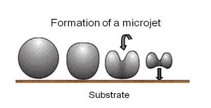
cavitation - bubble collapse-minWhen the cavitation bubbles collapse, they force energetic liquid into very small volumes, thereby creating spots of high temperature and emitting shock waves, the latter of which are a source of noise. Although the collapse of a small cavity is a relatively low-energy event, highly localized collapses can erode metals, such as steel, over time. The pitting caused by the collapse of cavities produces great wear on components and can dramatically shorten a propeller or pump’s lifetime.

Cavitation is usually accompanied also by:

  • Noise. Typical noise is caused by collapsing cavities. The level of the noise that results from cavitation is a measure of the severity of the cavitation.
  • Vibration.  Pump vibrations due to cavitation are characteristically low frequency vibrations, usually found in the 0 to 10 Hz range.
  • Reduction in pump efficiency. A decrease in efficiency of the pump is a more reliable sign of cavitation occurring.

Prevention of Cavitation

Pits can vary in size from very small to very large, or even they can completely penetrate the thickness of a metal. Damage to the structure can be catastrophic and losses in functional efficiency can be substantial. Methods of dealing with this problem include:

  • Increasing the hardness and strength of the metal. However, this may only delay the problem rather than prevent it.
  • Increasing the stiffness of the part. This should reduce its amplitude of vibration, thereby increasing its natural vibration frequency. It may be possible to increase wall thickness or add stiffening ribs to change vibration characteristics.
  • Increasing the smoothness of the surface. Cavities tend to cluster in certain low-pressure areas. It may be possible to eliminate surface peaks and valleys by dispersing the cavities.

Diffusive wear

Diffusion or dissolution wear refers to the damage, erosion or degradation of materials that occurs on a metal’s surface due to increased surface temperatures. When two materials are in contact with each other, atoms from one material could diffuse into the other, causing diffusion or dissolution wear. Diffusive wear is primarily due to the heat that is produced by adhesion when two rough surfaces move across each other, typically when one metal is sliding across the another one.

References:

Materials Science:

  1. U.S. Department of Energy, Material Science. DOE Fundamentals Handbook, Volume 1 and 2. January 1993.
  2. U.S. Department of Energy, Material Science. DOE Fundamentals Handbook, Volume 2 and 2. January 1993.
  3. William D. Callister, David G. Rethwisch. Materials Science and Engineering: An Introduction 9th Edition, Wiley; 9 edition (December 4, 2013), ISBN-13: 978-1118324578.
  4. Eberhart, Mark (2003). Why Things Break: Understanding the World by the Way It Comes Apart. Harmony. ISBN 978-1-4000-4760-4.
  5. Gaskell, David R. (1995). Introduction to the thermodynamics of Materials (4th ed.). Taylor and Francis Publishing. ISBN 978-1-56032-992-3.
  6. González-Viñas, W. & Mancini, H.L. (2004). An Introduction to Materials Science. Princeton University Press. ISBN 978-0-691-07097-1.
  7. Ashby, Michael; Hugh Shercliff; David Cebon (2007). Materials: engineering, science, processing and design (1st ed.). Butterworth-Heinemann. ISBN 978-0-7506-8391-3.
  8. J. R. Lamarsh, A. J. Baratta, Introduction to Nuclear Engineering, 3d ed., Prentice-Hall, 2001, ISBN: 0-201-82498-1.

See above:
Wear

We hope, this article, Wear Types – Classification and Differences, helps you. If so, give us a like in the sidebar. Main purpose of this website is to help the public to learn some interesting and important information about materials and their properties.
What is Tribology – Definition

Tribology is interdisciplinar science of interacting surfaces in relative motion. Tribology includes the study and application of the principles of friction, lubrication, and wear under applied load.

wearIn general, wear is mechanically induced surface damage that results in the progressive removal of material due to relative motion between that surface and a contacting substance or substances. A contacting substance may consist of another surface, a fluid, or hard, abrasive particles contained in some form of fluid or suspension, such as a lubricant for example. As is with friction, the presence of wear can be either good or bad. Productive, controlled wear can be found in processes like machining, cutting, grinding and polishing. However, in most of the technological applications, the occurrence of wear is highly undesirable and it is an enormously expensive problem since it leads to the deterioration or even failure of components. In terms of safety it is often not as serious (or as sudden) as fracture. This is because wear is usually anticipated.

Certain material characteristics such as hardness, carbide type, and volume percent can have a decided impact on the wear resistance of a material in a given application. Wear, like corrosion, has multiple types and subtypes, is predictable to some extent, and is rather difficult to reliably test and to evaluate in the lab or in service.

Tribology

Tribology is interdisciplinar science of interacting surfaces in relative motion. Tribology includes the study and application of the principles of friction, lubrication, and wear under applied load. Efficient operation and robust performance of these machine components are highly dependent on tribology. Controlling friction helps to reduce energy loss and improve efficiency and lifetime of a machines. Wear of material from a surface can lead to severe damage and failure of the component and/or the machine. The most common approach to reduce friction and minimize wear and catastrophic failure of machine components or the machine itself is by a proper selection of materials and lubricants. In most machine components, lubricants are used to reduce friction and prevent wear.

References:

Materials Science:

  1. U.S. Department of Energy, Material Science. DOE Fundamentals Handbook, Volume 1 and 2. January 1993.
  2. U.S. Department of Energy, Material Science. DOE Fundamentals Handbook, Volume 2 and 2. January 1993.
  3. William D. Callister, David G. Rethwisch. Materials Science and Engineering: An Introduction 9th Edition, Wiley; 9 edition (December 4, 2013), ISBN-13: 978-1118324578.
  4. Eberhart, Mark (2003). Why Things Break: Understanding the World by the Way It Comes Apart. Harmony. ISBN 978-1-4000-4760-4.
  5. Gaskell, David R. (1995). Introduction to the thermodynamics of Materials (4th ed.). Taylor and Francis Publishing. ISBN 978-1-56032-992-3.
  6. González-Viñas, W. & Mancini, H.L. (2004). An Introduction to Materials Science. Princeton University Press. ISBN 978-0-691-07097-1.
  7. Ashby, Michael; Hugh Shercliff; David Cebon (2007). Materials: engineering, science, processing and design (1st ed.). Butterworth-Heinemann. ISBN 978-0-7506-8391-3.
  8. J. R. Lamarsh, A. J. Baratta, Introduction to Nuclear Engineering, 3d ed., Prentice-Hall, 2001, ISBN: 0-201-82498-1.

See above:
Wear

We hope, this article, Tribology, helps you. If so, give us a like in the sidebar. Main purpose of this website is to help the public to learn some interesting and important information about materials and their properties.
What is Surface Hardness and Wear Resistance – Definition

Hardness is important from an engineering standpoint because resistance to wear by either friction or erosion by steam, oil, and water generally increases with hardness.

wearIn general, wear is mechanically induced surface damage that results in the progressive removal of material due to relative motion between that surface and a contacting substance or substances. A contacting substance may consist of another surface, a fluid, or hard, abrasive particles contained in some form of fluid or suspension, such as a lubricant for example. As is with friction, the presence of wear can be either good or bad. Productive, controlled wear can be found in processes like machining, cutting, grinding and polishing. However, in most of the technological applications, the occurrence of wear is highly undesirable and it is an enormously expensive problem since it leads to the deterioration or even failure of components. In terms of safety it is often not as serious (or as sudden) as fracture. This is because wear is usually anticipated.

Certain material characteristics such as hardness, carbide type, and volume percent can have a decided impact on the wear resistance of a material in a given application. Wear, like corrosion, has multiple types and subtypes, is predictable to some extent, and is rather difficult to reliably test and to evaluate in the lab or in service.

Surface Hardness and Wear Resistance

Hardness is important from an engineering standpoint because resistance to wear by either friction or erosion by steam, oil, and water generally increases with hardness. If the hardness of the material is higher than that of the abrasive material, less wear rate will occur.

Case hardening or surface hardening is the process in which hardness the surface (case) of an object is enhanced, while the inner core of the object remains elastic and tough. After this process surface hardness, wear-resistance and fatigue life are enhanced. This is accomplished by several processes such as a carburizing or nitriding process by which a component is exposed to a carbonaceous or nitrogenous atmosphere at elevated temperature. As was written, two main material characteristics are influenced:

  • Hardness and wear resistance is significantly enhanced. In materials science, hardness is the ability to withstand surface indentation (localized plastic deformation) and scratching. Hardness is probably the most poorly defined material property because it may indicate resistance to scratching, resistance to abrasion, resistance to indentation or even resistance to shaping or localized plastic deformation. Hardness is important from an engineering standpoint because resistance to wear by either friction or erosion by steam, oil, and water generally increases with hardness.
  • Toughness is not negatively influenced. Toughness is the ability of a material to absorb energy and plastically deform without fracturing. One definition of toughness (for high-strain rate, fracture toughness) is that it is a property that is indicative of a material’s resistance to fracture when a crack (or other stress-concentrating defect) is present.

For iron or steel with low carbon content, which has poor to no hardenability of its own, the case-hardening process involves infusing additional carbon or nitrogen into the surface layer. Case hardening is useful in parts such as a cam or ring gear that must have a very hard surface to resist wear, along with a tough interior to resist the impact that occurs during operation. Further, the surface hardening of steel has an advantage over through hardening (that is, hardening the metal uniformly throughout the piece) because less expensive low-carbon and medium-carbon steels can be surface hardened without the problems of distortion and cracking associated with the through hardening of thick sections. A carbon- or nitrogen-rich outer surface layer (or case) is introduced by atomic diffusion from the gaseous phase. The case is normally on the order of 1 mm deep and is harder than the inner core of material.

References:

Materials Science:

  1. U.S. Department of Energy, Material Science. DOE Fundamentals Handbook, Volume 1 and 2. January 1993.
  2. U.S. Department of Energy, Material Science. DOE Fundamentals Handbook, Volume 2 and 2. January 1993.
  3. William D. Callister, David G. Rethwisch. Materials Science and Engineering: An Introduction 9th Edition, Wiley; 9 edition (December 4, 2013), ISBN-13: 978-1118324578.
  4. Eberhart, Mark (2003). Why Things Break: Understanding the World by the Way It Comes Apart. Harmony. ISBN 978-1-4000-4760-4.
  5. Gaskell, David R. (1995). Introduction to the thermodynamics of Materials (4th ed.). Taylor and Francis Publishing. ISBN 978-1-56032-992-3.
  6. González-Viñas, W. & Mancini, H.L. (2004). An Introduction to Materials Science. Princeton University Press. ISBN 978-0-691-07097-1.
  7. Ashby, Michael; Hugh Shercliff; David Cebon (2007). Materials: engineering, science, processing and design (1st ed.). Butterworth-Heinemann. ISBN 978-0-7506-8391-3.
  8. J. R. Lamarsh, A. J. Baratta, Introduction to Nuclear Engineering, 3d ed., Prentice-Hall, 2001, ISBN: 0-201-82498-1.

See above:
Wear

We hope, this article, Surface Hardness and Wear Resistance, helps you. If so, give us a like in the sidebar. Main purpose of this website is to help the public to learn some interesting and important information about materials and their properties.
What is Fatigue Limit – Fatigue Strength – Definition

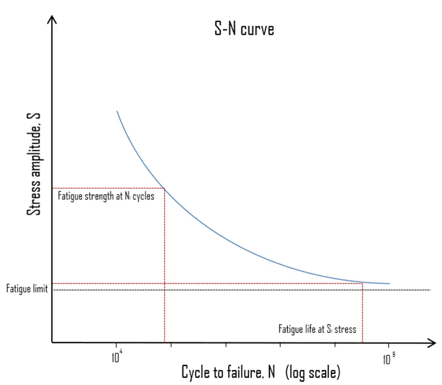
Fatigue limit (also sometimes called the endurance limit) is the stress level, below which fatigue failure does not occur. The ASTM defines fatigue strength, SNf, as the value of stress at which failure occurs after some specified number of cycles.

S-N curve - Fatigue Failure

The American Society for Testing and Materials defines fatigue life, Nf, as the number of stress cycles of a specified character that a specimen sustains before failure of a specified nature occurs. Fatigue life is affected by cyclic stresses, residual stresses, material properties, internal defects, grain size, temperature, design geometry, surface quality, oxidation, corrosion, etc. For some materials, notably steel and titanium, there is a theoretical value for stress amplitude below which the material will not fail for any number of cycles, called a fatigue limit, endurance limit, or fatigue strength.

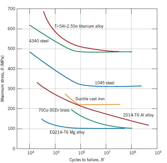
Engineers use a number of methods to determine the fatigue life of a material. One of the most useful is the stress-life method, is commonly characterized by an S-N curve, also known as a Wöhler curve. This method is illustrated in the figure It plots applied stress (S) against component life or number of cycles to failure (N). As the stress decreases from some high value, component life increases slowly at first and then quite rapidly. Because fatigue like brittle fracture has such a variable nature, the data used to plot the curve will be treated statistically. The scatter in results is a consequence of the fatigue sensitivity to a number of test and material parameters that are impossible to control precisely.

The following terms are defined for S-N curve:

  • Fatigue Limit. Fatigue limit (also sometimes called the endurance limit) is the stress level, below which fatigue failure does not occur. This limit exists only for some ferrous (iron-base) and titanium alloys, for which the S–N curve becomes horizontal at higher N values. Other structural metals, such as aluminium and copper, do not have a distinct limit and will eventually fail even from small stress amplitudes. Typical values of the limit for steels are 1/2 the ultimate tensile strength, to a maximum of 290 MPa (42 ksi).
  • Fatigue Strength. The ASTM defines fatigue strength, SNf, as the value of stress at which failure occurs after some specified number of cycles (e.g., 107 cycles) For example, the fatigue strength for annealed Ti-6Al-4V titanium alloy is about 240 MPa at 107 cycles and the stress concentration factor = 3.3.
  • Fatigue Life. Fatigue life characterizes a material’s fatigue behavior. It is the number of cycles to cause failure at a specified stress level, as taken from the S–N plot

The process of fatigue failure is characterized by three distinct steps:

  • Crack initiation, in which a small crack forms at some point of high stress concentration.
  • Crack propagation, during which this crack advances incrementally with each stress cycle. Most of the fatigue life is generally consumed in the crack growth phase.
  • Ultimate failure, which occurs very rapidly once the advancing crack has reached a critical size.

Cracks associated with fatigue failure almost always initiate (or nucleate) on the surface of a component at some point of stress concentration. Anything which leads to stress concentration, and the development of cracks, will reduce fatigue life. Therefore, increasing the degree of surface finish, polishing as compared to grinding, improves fatigue life. Increasing the strength and hardness of the surface layers of metal components will also improve fatigue life.

S-N curves of different materials
Maximum stress (S) versus logarithm of the number of cycles to fatigue failure (N) for seven metal alloys. Curves were generated using rotating–bending and reversed-cycle tests. Source: William D. Callister, David G. Rethwisch. Materials Science and Engineering: An Introduction 9th Edition, Wiley; 9 edition (December 4, 2013), ISBN-13: 978-1118324578.
References:

Materials Science:

  1. U.S. Department of Energy, Material Science. DOE Fundamentals Handbook, Volume 1 and 2. January 1993.
  2. U.S. Department of Energy, Material Science. DOE Fundamentals Handbook, Volume 2 and 2. January 1993.
  3. William D. Callister, David G. Rethwisch. Materials Science and Engineering: An Introduction 9th Edition, Wiley; 9 edition (December 4, 2013), ISBN-13: 978-1118324578.
  4. Eberhart, Mark (2003). Why Things Break: Understanding the World by the Way It Comes Apart. Harmony. ISBN 978-1-4000-4760-4.
  5. Gaskell, David R. (1995). Introduction to the thermodynamics of Materials (4th ed.). Taylor and Francis Publishing. ISBN 978-1-56032-992-3.
  6. González-Viñas, W. & Mancini, H.L. (2004). An Introduction to Materials Science. Princeton University Press. ISBN 978-0-691-07097-1.
  7. Ashby, Michael; Hugh Shercliff; David Cebon (2007). Materials: engineering, science, processing and design (1st ed.). Butterworth-Heinemann. ISBN 978-0-7506-8391-3.
  8. J. R. Lamarsh, A. J. Baratta, Introduction to Nuclear Engineering, 3d ed., Prentice-Hall, 2001, ISBN: 0-201-82498-1.

See above:
Fatigue

We hope, this article, Fatigue Limit – Fatigue Strength, helps you. If so, give us a like in the sidebar. Main purpose of this website is to help the public to learn some interesting and important information about materials and their properties.

What is Wear – Definition

In general, wear is mechanically induced surface damage that results in the progressive removal of material due to relative motion between that surface and a contacting substance or substances.

wearIn general, wear is mechanically induced surface damage that results in the progressive removal of material due to relative motion between that surface and a contacting substance or substances. A contacting substance may consist of another surface, a fluid, or hard, abrasive particles contained in some form of fluid or suspension, such as a lubricant for example. As is with friction, the presence of wear can be either good or bad. Productive, controlled wear can be found in processes like machining, cutting, grinding and polishing. However, in most of the technological applications, the occurrence of wear is highly undesirable and it is an enormously expensive problem since it leads to the deterioration or even failure of components. In terms of safety it is often not as serious (or as sudden) as fracture. This is because wear is usually anticipated.

Certain material characteristics such as hardness, carbide type, and volume percent can have a decided impact on the wear resistance of a material in a given application. Wear, like corrosion, has multiple types and subtypes, is predictable to some extent, and is rather difficult to reliably test and to evaluate in the lab or in service.

Tribology

Tribology is interdisciplinar science of interacting surfaces in relative motion. Tribology includes the study and application of the principles of friction, lubrication, and wear under applied load. Efficient operation and robust performance of these machine components are highly dependent on tribology. Controlling friction helps to reduce energy loss and improve efficiency and lifetime of a machines. Wear of material from a surface can lead to severe damage and failure of the component and/or the machine. The most common approach to reduce friction and minimize wear and catastrophic failure of machine components or the machine itself is by a proper selection of materials and lubricants. In most machine components, lubricants are used to reduce friction and prevent wear.

Surface Hardness and Wear Resistance

Hardness is important from an engineering standpoint because resistance to wear by either friction or erosion by steam, oil, and water generally increases with hardness. If the hardness of the material is higher than that of the abrasive material, less wear rate will occur.

Case hardening or surface hardening is the process in which hardness the surface (case) of an object is enhanced, while the inner core of the object remains elastic and tough. After this process surface hardness, wear-resistance and fatigue life are enhanced. This is accomplished by several processes such as a carburizing or nitriding process by which a component is exposed to a carbonaceous or nitrogenous atmosphere at elevated temperature. As was written, two main material characteristics are influenced:

  • Hardness and wear resistance is significantly enhanced. In materials science, hardness is the ability to withstand surface indentation (localized plastic deformation) and scratching. Hardness is probably the most poorly defined material property because it may indicate resistance to scratching, resistance to abrasion, resistance to indentation or even resistance to shaping or localized plastic deformation. Hardness is important from an engineering standpoint because resistance to wear by either friction or erosion by steam, oil, and water generally increases with hardness.
  • Toughness is not negatively influenced. Toughness is the ability of a material to absorb energy and plastically deform without fracturing. One definition of toughness (for high-strain rate, fracture toughness) is that it is a property that is indicative of a material’s resistance to fracture when a crack (or other stress-concentrating defect) is present.

For iron or steel with low carbon content, which has poor to no hardenability of its own, the case-hardening process involves infusing additional carbon or nitrogen into the surface layer. Case hardening is useful in parts such as a cam or ring gear that must have a very hard surface to resist wear, along with a tough interior to resist the impact that occurs during operation. Further, the surface hardening of steel has an advantage over through hardening (that is, hardening the metal uniformly throughout the piece) because less expensive low-carbon and medium-carbon steels can be surface hardened without the problems of distortion and cracking associated with the through hardening of thick sections. A carbon- or nitrogen-rich outer surface layer (or case) is introduced by atomic diffusion from the gaseous phase. The case is normally on the order of 1 mm deep and is harder than the inner core of material.

Wear Coefficient

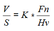
Wear can be quantified (correlated) by means of wear rate, defined as the mass or volume of material removed per unit sliding distance. It is usually expressed in terms of the dimensionless wear coefficient (K) or as specific wear rate (wear volume per unit applied normal load per unit sliding distance) in (mm3*Nm-1).

The most commonly used wear equation for the dry rolling–sliding condition is Archards wear equation. The wear volume (V), for unit sliding distance (S) is equal to the non-dimensional wear coefficient (K) multiplied by the applied load (Fn) divided by the hardness of the worn material.

wear coefficient

Wear Types

Wear is commonly classified according to so-called wear types, which occur in isolation or complex interaction. Wear mechanisms and/or sub-mechanisms frequently overlap and occur in a synergistic manner, producing a greater rate of wear than the sum of the individual wear mechanisms. The most common wear types are:

Other, less common types of wear are:

Abrasive Wear

Abrasive wear is defined as the loss of material due to hard particles or hard protuberances that are forced against and move along a solid surface. It occurs when a hard rough surface slides across a softer surface. This mechanism is sometimes referred to as grinding wear. The harder material may be one of the rubbing surfaces or hard particles that have found their way between the mating surfaces. These may be ‘foreign’ particles or particles resulting from adhesive or delamination wear. Abrasion mainly involves microscale cutting and plowing processes. The way an asperity slides over a surface determines the nature and intensity of abrasive wear. There are two basic modes of abrasive wear:

  • Two-body abrasive wear. Two-body wear occurs when the grits or hard particles remove material from the opposite surface. The common analogy is that of material being removed or displaced by a cutting or plowing operation.
  • Three-body abrasive wear. Three-body wear occurs when the particles are not constrained, and are free to roll and slide down a surface. The contact environment determines whether the wear is classified as open or closed. An open contact environment occurs when the surfaces are sufficiently displaced to be independent of one another.

There are a number of different strategies for mitigating abrasive wear, but the general rule for materials selection is, the harder the better. Materials that contain a relatively large percentage of hard, wear-resistant alloy carbides, such as selected tool steels and high-speed steels.

Adhesive Wear

Adhesive wear is originated through the bonding of asperities or microscopic high points (surface roughness) between two sliding materials. When a peak from one surface comes into contact with a peak from the other surface, instantaneous microwelding may take place due to the heat generated by the resulting friction. This results in detachment or material transfer from one surface to the other. For adhesive wear to occur it is necessary for the surfaces to be in intimate contact with each other. This may cause unwanted displacement and attachment of wear debris and material compounds from one surface to another. Adhesive wear can lead to an increase in roughness and the creation of protrusions (i.e., lumps) above the original surface. Surfaces which are held apart by lubricating films, oxide films etc. reduce the tendency for adhesion to occur. In some engineering applications, surfaces slide in air or without lubricant and the resulting wear is termed as dry sliding.

Adhesive wear is dependent on the materials involved, the degree of lubrication provided, and the environment. Adequate lubrication allows smooth, continuous operation of machine elements, reduces the rate of wear, and prevents excessive stresses or seizures at bearings. When lubrication breaks down, components can rub destructively against each other, causing heat, local welding, destructive damage and failure. For instance, austenitic stainless steels (e.g. AISI 304) sliding against themselves are very likely to transfer material and gall, resulting in severe surface damage. Other materials that are prone to adhesive wear include titanium, nickel, and zirconium. On the other hand, aluminium bronze has found increasing recognition for a wide variety of applications requiring resistance to mechanical wear. Its wear-resistance is based on the transfer from the softer metal (aluminium bronze) to the harder metal (steel) and formation of thin layer of softer metal on the harder metal.

For example, the main function of motor oil is to reduce friction and wear on moving parts (to reduce adhesive wear) and to clean the engine from sludge, while a filter is designed to remove contaminants and abrasive particles from engine oil.

Erosion Wear

Erosion wear is a process of progressive removal of material from a target surface due to repeated impacts of solid particles. The particles suspended in the flow of solid liquid mixture erode the wetted passes limiting the service life of equipment used for slurry transportation system. Each particle cuts or fractures a tiny amount of material (referred to as wear chips) from the surface. If this is repeated over a long period of time, a significant amount of material loss can result.

Erosive wear is common in pumps and impellers, fans, steam lines and nozzles, on the inside of sharp bends in tubes and pipes. Therefore, it is a widely encountered mechanism in industry and power engineering. Due to the nature of the conveying process, piping systems are prone to wear when abrasive particles have to be transported.

Erosion wear is caused by the kinetic energy transferred to target surface by impinging solid particles. The rate of erosive wear is dependent upon a number of factors. The material characteristics of the particles, such as their shape, hardness, impact velocity and impingement angle are primary factors along with the properties of the surface being eroded. Material loss of target material is higher for higher kinetic energy of impinging particle. So impact velocity largely affects the erosion wear of target material. The impingement angle is one of the most important factors and is widely recognized in literature. Sharp curves or bends tend to produce more erosion than gentle curves.

Erosion wear can be classified into three categories:

  • Solid particle erosion. Solid particle erosion is the loss of material volume from target material due to continues impingement of solid particles present in the flowing fluid.
  • Liquid impact erosion. The continues striking of liquid jet on material surface cause liquid impact erosion.
  • Cavitations erosion. When the vapor or gas in a liquid forms cavities or bubbles that cause wear.

In general, erosive wear resistance may be improved by increasing the hardness of the surface, by proper materials and proper design of the product. Some specific steps that can be taken to change flow conditions include: reducing fluid velocity, eliminating turbulence at misalignments and avoiding sharp bends.

Erosion – Corrosion

Erosion can also occur in combination with other forms of degradation, such as corrosion. This is referred to as erosion-corrosion. Erosion corrosion is a material degradation process due to the combined effect of corrosion and wear. Nearly all flowing or turbulent corrosive media can cause erosion corrosion. The mechanism can be described as follows:

  • mechanical erosion of the material, or protective (or passive) oxide layer on its surface,
  • enhanced corrosion of the material, if the corrosion rate of the material depends on the thickness of the oxide layer.

Wear is a mechanical material degradation process occurring on rubbing or impacting surfaces, while corrosion involves chemical or electrochemical reactions of the material. Corrosion may accelerate wear and wear may accelerate corrosion.

Fretting Wear

Fretting wear is a special wear process that occurs at the contact area between two materials under load and subject to minute relative motion by vibration or some other force. Fretting wear is similar to adhesive wear in that microwelding occurs on mating surfaces. In adhesive wear, however, facing metals slide across each other, while in fretting wear metal-to-metal interfaces are essentially stationary. The amplitude of the relative sliding motion is often in the order from micrometers to millimeters. Because fretting wear is essentially a stationary phenomenon, debris is retained at or near the locations where it was formed originally. This debris usually consists of oxides of the metals in contact. Because the oxidized debris is usually much harder than the surfaces from which it came, it often acts as an abrasive agent that increases the rate of fretting. Fretting wear occurs typically in bearings, although most bearings have their surfaces hardened to resist the problem.

 Fretting mitigation is based on following measures:

  • Reduce or eliminate vibration. The fundamental way to prevent fretting is to design for no relative motion of the surfaces at the contact
  • Use of an elastomeric material to prevent metal-to-metal contact.
  • Lubrication. The problem here is that because the joint is essentially stationary, liquid lubricant cannot flow through the in terface.

Debris Fretting – Grid-to-rod Fretting

In nuclear power plants, fuel cladding is the outer layer of the fuel rods, standing between the reactor coolant and the nuclear fuel (i.e. fuel pellets). It is made of a corrosion-resistant material with low absorption cross section for thermal neutrons (~ 0.18 × 10⁻²⁴ cm2), usually zirconium alloy. Cladding prevents radioactive fission products from escaping the fuel matrix into the reactor coolant and contaminating it. In the early dates of PWR and BWR operations, fretting was one of main failure mechanisms of this fuel cladding. It has typically two variants.

  • Debris fretting. Debris fretting can be caused by any debris (foregn material – usually metallic) that can enter the fuel bundle and that has the potential of becoming lodged between the spacer grid and a fuel rod. Fretting wear of fuel cladding can results in cladding penetration.
  • Grid-to-rod fretting. Grid-to-rod fretting arises from vibration of the fuel element generated by the high coolant velocity through the spacing grid. Spacing grids are welded onto the guide tubes and ensure, by means of springs and dimples, fuel rod support, and spacing. High coolant velocity can cause the rod to rub against the part of the spacer grid that holds it. This type of cladding wear can be minimized by proper design of the spacing grid. Baffle-jetting is usually grouped under grid-to-rod fretting.

See also: IAEA, Review of fuel failures in water cooled reactors. No. NF-T-2.1. ISBN 978–92–0–102610–1, Vienna, 2010.

Surface Fatigue – Fatigue Wear

In materials science, fatigue is the weakening of a material caused by cyclic loading that results in progressive, brittle and localized structural damage. Surface fatigue, or fatigue wear, is the cracking and subsequent pitting of surfaces subjected to alternating stresses during rolling contact or the stresses from combined rolling and sliding. Fatigue wear is produced when the wear particles are detached by cyclic crack growth of microcracks on the surface. These microcracks are either superficial cracks or subsurface cracks. The repeated loading and unloading cycles to which the materials are exposed may induce the formation of subsurface or surface cracks, which eventually, after a critical number of cycles, will result in the breakup of the surface with the formation of large fragments, leaving large pits in the surface. Once a crack has initiated, each loading cycle will grow the crack a small amount, even when repeated alternating or cyclic stresses are of an intensity considerably below the normal strength. The stresses could be due to vibration or thermal cycling. Subsurface and surface fatigues are observed during repeated rolling and sliding, respectively.

Corrosive and oxidation wear

Corrosive wear is a material degradation process due to the combined effect of corrosion and wear. It is defined as the wear process in which sliding takes place in a corrosive environment. In the absence of sliding, the products of the corrosion (e.g., oxides) would form a film typically less than a micrometer thick on the surfaces, which would tend to slow down or even eliminate the corrosion, but the sliding action wears the film away, so that further corrosion can continue. Oxidation wear is one of the most common forms of corrosive wear, because an oxygen-rich environment is a typical environment in which this wear process occurs. Corrosive wear requires both corrosion and rubbing. Chemical corrosion occurs in a highly corrosive environment and in high temperature and high humidity environments.

Erosion – Corrosion

Erosion can also occur in combination with other forms of degradation, such as corrosion. This is referred to as erosion-corrosion. Erosion corrosion is a material degradation process due to the combined effect of corrosion and wear. Nearly all flowing or turbulent corrosive media can cause erosion corrosion. The mechanism can be described as follows:

  • mechanical erosion of the material, or protective (or passive) oxide layer on its surface,
  • enhanced corrosion of the material, if the corrosion rate of the material depends on the thickness of the oxide layer.

Wear is a mechanical material degradation process occurring on rubbing or impacting surfaces, while corrosion involves chemical or electrochemical reactions of the material. Corrosion may accelerate wear and wear may accelerate corrosion.

Impact Wear

Impact wear is defined as the wear of a solid surface that is due to percussion, which is repetitive exposure to dynamic contact by another solid body. Impact wear is of the highest impostance in mining nad mineral processing. Mining and mineral processing demand wear-resistant machines and components, because the energies and masses of interacting bodies are significant. For this purposes, materials with the highest wear-resistance must be used. For example, tungsten carbide is used extensively in mining in top hammer rock drill bits, downhole hammers, roller-cutters, long wall plough chisels, long wall shearer picks, raiseboring reamers, and tunnel boring machines.

For metal impact pairs, the behavior of impact wear involves elastic and plastic deformation when impact loading or impact energy is high and/or fatigue accompanied by wear debris release due to crack formation. In general, impact wear of metals is dependent on the formation of deformed layers, particularly when wear by fatigue or crack formation is predominant. In such cases, subsurface cracks extend parallel to the surface in a manner very similar to delamination wear. Sufficient hardness of the impacted component is necessary to prevent rapid wear or extrusion of material from the contact by plastic deformation. In most situations this condition can be fulfilled by assuring an adequate hardness and then wear is controlled by other material characteristics.

Cavitation wear

Cavitation wear is a process of progressive degradation of material due to repeated nucleation, growth, and violent collapse of cavities in a liquid flowing near the material. Cavitation fatigue is a specific type of damage mechanism caused by repeated vibration and movement due to contact with flowing liquids, with water being the most common fluid. Cavitation is, in many cases, an undesirable occurrence. In centrifugal pumps, cavitation causes damage to components (erosion of the material), vibrations, noise and a loss of efficiency.

Source: Wikipedia, CC BY 2.5,
https://commons.wikimedia.org/wiki/File:Turbine_Francis_Worn.JPG

Perhaps the most important engineering problem caused by cavitation is the material damage that cavitation bubbles can cause when they collapse in the vicinity of a solid surface.  Cavitation bubbles collapse is a violent process that generates highly localized shock waves and microjets. They force energetic liquid into very small volumes, thereby creating spots of high temperature and these intense disturbances generate highly localized and transient surface stresses to a solid surface. Signs of erosion will appear as pitting due to the waterhammering action of the collapsing vapour bubbles. It has been found that cavitation damage rates increase rapidly with the increase in the volume flow rate.

Softer materials can be damaged even by short-term occurrance of cavitation.  Individual pits can be observed after a single bubble collapse. Therefore harder materials are used for centrifugal pumps. But with the harder materials used in most applications, the cyclic stress due to repeated collapses can cause local surface fatigue failure. Thus cavitation damage to metals usually has the appearance of fatigue failure.

cavitation - bubble collapse-minWhen the cavitation bubbles collapse, they force energetic liquid into very small volumes, thereby creating spots of high temperature and emitting shock waves, the latter of which are a source of noise. Although the collapse of a small cavity is a relatively low-energy event, highly localized collapses can erode metals, such as steel, over time. The pitting caused by the collapse of cavities produces great wear on components and can dramatically shorten a propeller or pump’s lifetime.

Cavitation is usually accompanied also by:

  • Noise. Typical noise is caused by collapsing cavities. The level of the noise that results from cavitation is a measure of the severity of the cavitation.
  • Vibration.  Pump vibrations due to cavitation are characteristically low frequency vibrations, usually found in the 0 to 10 Hz range.
  • Reduction in pump efficiency. A decrease in efficiency of the pump is a more reliable sign of cavitation occurring.

Prevention of Cavitation

Pits can vary in size from very small to very large, or even they can completely penetrate the thickness of a metal. Damage to the structure can be catastrophic and losses in functional efficiency can be substantial. Methods of dealing with this problem include:

  • Increasing the hardness and strength of the metal. However, this may only delay the problem rather than prevent it.
  • Increasing the stiffness of the part. This should reduce its amplitude of vibration, thereby increasing its natural vibration frequency. It may be possible to increase wall thickness or add stiffening ribs to change vibration characteristics.
  • Increasing the smoothness of the surface. Cavities tend to cluster in certain low-pressure areas. It may be possible to eliminate surface peaks and valleys by dispersing the cavities.

Diffusive wear

Diffusion or dissolution wear refers to the damage, erosion or degradation of materials that occurs on a metal’s surface due to increased surface temperatures. When two materials are in contact with each other, atoms from one material could diffuse into the other, causing diffusion or dissolution wear. Diffusive wear is primarily due to the heat that is produced by adhesion when two rough surfaces move across each other, typically when one metal is sliding across the another one.

Typical Wear-resistant Materials

In general, wear is mechanically induced surface damage that results in the progressive removal of material due to relative motion between that surface and a contacting substance or substances. Therefore, there is perfect wear-resistant material and in every case, it depends strongly on many variables (e.g. materials combination, contact pressure, environment, temperature). The hardness of the material is correlated to the wear resistance of the material. If  the hardness of the material is less than that of the hardness of the abrasive material, then the wear rate is high. The hardness of material plays a major role in wear resistance. Some materials exhibit special wear characteristics:

  • Ni3Al – Alloy. Nickel aluminide is an intermetallic alloy of nickel and aluminium with properties similar to both a ceramic and a metal. Nickel aluminide is unique in that it has very high thermal conductivity combined with high strength at high temperature. These properties, combined with its high strength and low density, make it ideal for special applications like coating blades in gas turbines and jet engines. Composite materials with Ni3Al based alloys as a matrix hardened by, e.g., TiC, ZrO2, WC,SiC and graphene, are advanced materials. In 2005, the most abrasion-resistant material was reportedly created by embedding diamonds in a matrix of nickel aluminide.
  • Tungsten Carbide. Impact wear is of the highest impostance in mining nad mineral processing. Mining and mineral processing demand wear-resistant machines and components, because the energies and masses of interacting bodies are significant. For this purposes, materials with the highest wear-resistance must be used. For example, tungsten carbide is used extensively in mining in top hammer rock drill bits, downhole hammers, roller-cutters, long wall plough chisels, long wall shearer picks, raiseboring reamers, and tunnel boring machines.
  • Silicon Carbide. Silicon carbide is exceedingly hard, synthetically produced crystalline compound of silicon and carbon. Its chemical formula is SiC. Silicon carbide has a Mohs hardness rating of 9, approaching that of diamond. In addition to hardness, silicon carbide crystals have fracture characteristics that make them extremely useful in grinding wheels. Its high thermal conductivity, together with its high-temperature strength, low thermal expansion, and resistance to chemical reaction, makes silicon carbide valuable in the manufacture of high-temperature applications and other refractories.
  • Coated Alloys. Case hardening by surface treatment can be classified further as diffusion treatments or localized heating treatments. Diffusion methods introduce alloying elements that enter the surface by diffusion, either as solid-solution agents or as hardenability agents that assist martensite formation during subsequent quenching. In this process, the concentration of alloying element is increased at the surface of a steel component. Diffusion methods include:
  • Carburizing is a case hardening process in which the surface carbon concentration of a ferrous alloy (usually a low-carbon steel) is increased by diffusion from the surrounding environment. Carburizing produces hard, highly wear-resistant surface (medium case depths) of product with excellent capacity for contact load, good bending fatigue strength and good resistance to seizure.
  • Nitriding is a case hardening process in which the surface nitrogen concentration of a ferrous is increased by diffusion from the surrounding environment to create case-hardened surface. Nitriding produces hard, highly wear-resistant surface (shallow case depths) of product with fair capacity for contact load, good bending fatigue strength and excellent resistance to seizure.
  • Boriding, also called boronizing is a thermochemical diffusion process similar to nitrocarburising in which boron atoms diffuse into the substrate to produce hard and wear-resistant surface layers. The process requires a high treatment temperature (1073-1323 K) and long duration (1-12 h), and can be applied to a wide range of materials such as steels, cast iron, cermets, and non-ferrous alloys.
  • Titanium-carbon and Titanium-nitride Hardening. Titanium nitride (an extremely hard ceramic material), or titanium carbide coatings can be used in the tools made of this kind of steels through physical vapor deposition process to improve the performance and life span of the tool. TiN has a Vickers hardness of 1800–2100 and it has metallic gold color.
  • Induction hardeningCase Hardened Steels. In order to enhance wear resistance of steels, case hardening based on martensitic transformation is usually performed. Martensitic transformation hardening is one of most common methods of hardening, which is primarily used for steels (i.e. carbon steels as well as stainless steels).
  • Flame hardening. Flame hardening is a surface hardening technique which uses a single torch with a specially designed head to provide a very rapid means of heating the metal, which is then cooled rapidly, generally using water. This creates a “case” of martensite on the surface, while the inner core of the object remains elastic and tough. It is similar technique as induction hardening. A carbon content of 0.3–0.6 wt% C is needed for this type of hardening.
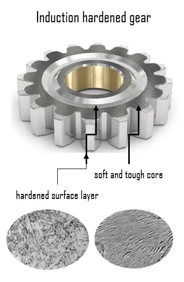
  • Induction hardening. Induction hardening is a surface hardening technique which uses induction coils to provide a very rapid means of heating the metal, which is then cooled rapidly, generally using water. This creates a “case” of martensite on the surface. A carbon content of 0.3–0.6 wt% C is needed for this type of hardening.
  • Laser hardening. Laser hardening is a surface hardening technique which uses a laser beam to provide a very rapid means of heating the metal, which is then cooled rapidly (generally by self-quenching). This creates a “case” of martensite on the surface, while the inner core of the object remains elastic and tough.


Some common materials:

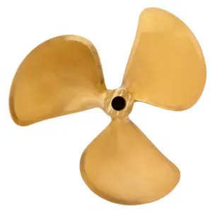
  • Nibral Propeller (nickel aluminium bronze) Source: generalpropeller.com
    Nibral Propeller (nickel aluminium bronze) Source: generalpropeller.com

    Ductile cast iron. Ductile iron, also known as nodular ironor spheroidal graphite iron, is very similar to gray iron in composition, but during solidification the graphite nucleates as spherical particles (nodules) in ductile iron, rather than as flakes. Typical applications for this material include valves, pump bodies, crankshafts, gears, and other automotive and machine components because of its good machinability, fatigue strength, and higher modulus of elasticity (compared to gray iron), and in heavy-duty gears because of its high yield strength and wear resistance.

  • Aluminium Bronze. The aluminium bronzes are a family of copper-based alloys offering a combination of mechanical and chemical properties unmatched by any other alloy series. They contain about 5 to 12% of aluminium. Aluminium bronze has found increasing recognition for a wide variety of applications requiring resistance to mechanical wear. Its wear-resistance is based on the transfer from the softer metal (aluminium bronze) to the harder metal (steel) and formation of thin layer of softer metal on the harder metal.
References:

Materials Science:

  1. U.S. Department of Energy, Material Science. DOE Fundamentals Handbook, Volume 1 and 2. January 1993.
  2. U.S. Department of Energy, Material Science. DOE Fundamentals Handbook, Volume 2 and 2. January 1993.
  3. William D. Callister, David G. Rethwisch. Materials Science and Engineering: An Introduction 9th Edition, Wiley; 9 edition (December 4, 2013), ISBN-13: 978-1118324578.
  4. Eberhart, Mark (2003). Why Things Break: Understanding the World by the Way It Comes Apart. Harmony. ISBN 978-1-4000-4760-4.
  5. Gaskell, David R. (1995). Introduction to the thermodynamics of Materials (4th ed.). Taylor and Francis Publishing. ISBN 978-1-56032-992-3.
  6. González-Viñas, W. & Mancini, H.L. (2004). An Introduction to Materials Science. Princeton University Press. ISBN 978-0-691-07097-1.
  7. Ashby, Michael; Hugh Shercliff; David Cebon (2007). Materials: engineering, science, processing and design (1st ed.). Butterworth-Heinemann. ISBN 978-0-7506-8391-3.
  8. J. R. Lamarsh, A. J. Baratta, Introduction to Nuclear Engineering, 3d ed., Prentice-Hall, 2001, ISBN: 0-201-82498-1.

See above:
Failure Modes

We hope, this article, Wear, helps you. If so, give us a like in the sidebar. Main purpose of this website is to help the public to learn some interesting and important information about materials and their properties.

What is High Cycle Fatigue vs Low Cycle Fatigue – Definition

Fatigue has been separated into regions of high cycle fatigue and low cycle fatigue. The chief difference between high cycle and low cycle fatigue is the number of cycles to failure. Transition between LCF and HCF is determined by the stress level, i.e. transition between plastic and elastic deformations.

In materials science, fatigue is the weakening of a material caused by cyclic loading that results in progressive, brittle and localized structural damage. Once a crack has initiated, each loading cycle will grow the crack a small amount, even when repeated alternating or cyclic stresses are of an intensity considerably below the normal strength. The stresses could be due to vibration or thermal cycling. Fatigue damage is caused by:

  • simultaneous action of cyclic stress,
  • tensile stress (whether directly applied or residual),
  • plastic strain.

If any one of these three is not present, a fatigue crack will not initiate and propagate. The majority of engineering failures are caused by fatigue.

High Cycle Fatigue vs Low Cycle Fatigue

Fatigue has been separated into regions of high cycle fatigue and low cycle fatigue. The chief difference between high cycle and low cycle fatigue is the number of cycles to failure. Transition between LCF and HCF is determined by the stress level, i.e. transition between plastic and elastic deformations.

  • High cycle fatigue require more than 104 cycles to failure where stress is low and primarily elastic.
  • Low cycle fatigue is characterized by repeated plastic deformation (i.e. in each cycle) and therefore, the number of cycles to failure is low. In the plastic region large changes in strain can be produced by small changes in stress. Experiments have shown that low cycle fatigue is also crack growth.

Fatigue failures, both for high and low cycle, all follow the same basic steps process of crack initiation, stage I crack growth, stage II crack growth, and finally ultimate failure.

References:

Materials Science:

  1. U.S. Department of Energy, Material Science. DOE Fundamentals Handbook, Volume 1 and 2. January 1993.
  2. U.S. Department of Energy, Material Science. DOE Fundamentals Handbook, Volume 2 and 2. January 1993.
  3. William D. Callister, David G. Rethwisch. Materials Science and Engineering: An Introduction 9th Edition, Wiley; 9 edition (December 4, 2013), ISBN-13: 978-1118324578.
  4. Eberhart, Mark (2003). Why Things Break: Understanding the World by the Way It Comes Apart. Harmony. ISBN 978-1-4000-4760-4.
  5. Gaskell, David R. (1995). Introduction to the thermodynamics of Materials (4th ed.). Taylor and Francis Publishing. ISBN 978-1-56032-992-3.
  6. González-Viñas, W. & Mancini, H.L. (2004). An Introduction to Materials Science. Princeton University Press. ISBN 978-0-691-07097-1.
  7. Ashby, Michael; Hugh Shercliff; David Cebon (2007). Materials: engineering, science, processing and design (1st ed.). Butterworth-Heinemann. ISBN 978-0-7506-8391-3.
  8. J. R. Lamarsh, A. J. Baratta, Introduction to Nuclear Engineering, 3d ed., Prentice-Hall, 2001, ISBN: 0-201-82498-1.

See above:
Fatigue

We hope, this article, High Cycle Fatigue vs Low Cycle Fatigue, helps you. If so, give us a like in the sidebar. Main purpose of this website is to help the public to learn some interesting and important information about materials and their properties.

What is Fatigue Life – S-N Curve – Woehler Curve – Definition

S-N curve, also known as a Wöhler curve plots applied stress (S) against component life or number of cycles to failure (N). Engineers use this method to determine the fatigue life of a material.

In materials science, fatigue is the weakening of a material caused by cyclic loading that results in progressive, brittle and localized structural damage. Once a crack has initiated, each loading cycle will grow the crack a small amount, even when repeated alternating or cyclic stresses are of an intensity considerably below the normal strength. The stresses could be due to vibration or thermal cycling. Fatigue damage is caused by:

  • simultaneous action of cyclic stress,
  • tensile stress (whether directly applied or residual),
  • plastic strain.

If any one of these three is not present, a fatigue crack will not initiate and propagate. The majority of engineering failures are caused by fatigue.

Although the fracture is of a brittle type, it may take some time to propagate, depending on both the intensity and frequency of the stress cycles. Nevertheless, there is very little, if any, warning before failure if the crack is not noticed. The number of cycles required to cause fatigue failure at a particular peak stress is generally quite large, but it decreases as the stress is increased. For some mild steels, cyclical stresses can be continued indefinitely provided the peak stress (sometimes called fatigue strength) is below the endurance limit value. A good example of fatigue failure is breaking a thin steel rod or wire with your hands after bending it back and forth several times in the same place. Another example is an unbalanced pump impeller resulting in vibrations that can cause fatigue failure. The type of fatigue of most concern in nuclear power plants is thermal fatigue. Thermal fatigue can arise from thermal stresses produced by cyclic changes in temperature. Large components like the pressurizer, reactor vessel, and reactor system piping are subject to cyclic stresses caused by temperature variations during reactor startup, change in power level, and shutdown.

Fatigue Life – S-N Curve

S-N curve - Fatigue Failure

The American Society for Testing and Materials defines fatigue life, Nf, as the number of stress cycles of a specified character that a specimen sustains before failure of a specified nature occurs. Fatigue life is affected by cyclic stresses, residual stresses, material properties, internal defects, grain size, temperature, design geometry, surface quality, oxidation, corrosion, etc. For some materials, notably steel and titanium, there is a theoretical value for stress amplitude below which the material will not fail for any number of cycles, called a fatigue limit, endurance limit, or fatigue strength.

Engineers use a number of methods to determine the fatigue life of a material. One of the most useful is the stress-life method, is commonly characterized by an S-N curve, also known as a Wöhler curve. This method is illustrated in the figure. It plots applied stress (S) against component life or number of cycles to failure (N). As the stress decreases from some high value, component life increases slowly at first and then quite rapidly. Because fatigue like brittle fracture has such a variable nature, the data used to plot the curve will be treated statistically. The scatter in results is a consequence of the fatigue sensitivity to a number of test and material parameters that are impossible to control precisely.

The following terms are defined for S-N curve:

  • Fatigue Limit. Fatigue limit (also sometimes called the endurance limit) is the stress level, below which fatigue failure does not occur. This limit exists only for some ferrous (iron-base) and titanium alloys, for which the S–N curve becomes horizontal at higher N values. Other structural metals, such as aluminium and copper, do not have a distinct limit and will eventually fail even from small stress amplitudes. Typical values of the limit for steels are 1/2 the ultimate tensile strength, to a maximum of 290 MPa (42 ksi).
  • Fatigue Strength. The ASTM defines fatigue strength, SNf, as the value of stress at which failure occurs after some specified number of cycles (e.g., 107 cycles) For example, the fatigue strength for annealed Ti-6Al-4V titanium alloy is about 240 MPa at 107 cycles and the stress concentration factor = 3.3.
  • Fatigue Life. Fatigue life characterizes a material’s fatigue behavior. It is the number of cycles to cause failure at a specified stress level, as taken from the S–N plot

The process of fatigue failure is characterized by three distinct steps:

  • Crack initiation, in which a small crack forms at some point of high stress concentration.
  • Crack propagation, during which this crack advances incrementally with each stress cycle. Most of the fatigue life is generally consumed in the crack growth phase.
  • Ultimate failure, which occurs very rapidly once the advancing crack has reached a critical size.

Cracks associated with fatigue failure almost always initiate (or nucleate) on the surface of a component at some point of stress concentration. Anything which leads to stress concentration, and the development of cracks, will reduce fatigue life. Therefore, increasing the degree of surface finish, polishing as compared to grinding, improves fatigue life. Increasing the strength and hardness of the surface layers of metal components will also improve fatigue life.

S-N curves of different materials
Maximum stress (S) versus logarithm of the number of cycles to fatigue failure (N) for seven metal alloys. Curves were generated using rotating–bending and reversed-cycle tests. Source: William D. Callister, David G. Rethwisch. Materials Science and Engineering: An Introduction 9th Edition, Wiley; 9 edition (December 4, 2013), ISBN-13: 978-1118324578.

High Cycle Fatigue vs Low Cycle Fatigue

Fatigue has been separated into regions of high cycle fatigue and low cycle fatigue. The chief difference between high cycle and low cycle fatigue is the number of cycles to failure. Transition between LCF and HCF is determined by the stress level, i.e. transition between plastic and elastic deformations.

  • High cycle fatigue require more than 104 cycles to failure where stress is low and primarily elastic.
  • Low cycle fatigue is characterized by repeated plastic deformation (i.e. in each cycle) and therefore, the number of cycles to failure is low. In the plastic region large changes in strain can be produced by small changes in stress. Experiments have shown that low cycle fatigue is also crack growth.

Fatigue failures, both for high and low cycle, all follow the same basic steps process of crack initiation, stage I crack growth, stage II crack growth, and finally ultimate failure.

References:

Materials Science:

  1. U.S. Department of Energy, Material Science. DOE Fundamentals Handbook, Volume 1 and 2. January 1993.
  2. U.S. Department of Energy, Material Science. DOE Fundamentals Handbook, Volume 2 and 2. January 1993.
  3. William D. Callister, David G. Rethwisch. Materials Science and Engineering: An Introduction 9th Edition, Wiley; 9 edition (December 4, 2013), ISBN-13: 978-1118324578.
  4. Eberhart, Mark (2003). Why Things Break: Understanding the World by the Way It Comes Apart. Harmony. ISBN 978-1-4000-4760-4.
  5. Gaskell, David R. (1995). Introduction to the thermodynamics of Materials (4th ed.). Taylor and Francis Publishing. ISBN 978-1-56032-992-3.
  6. González-Viñas, W. & Mancini, H.L. (2004). An Introduction to Materials Science. Princeton University Press. ISBN 978-0-691-07097-1.
  7. Ashby, Michael; Hugh Shercliff; David Cebon (2007). Materials: engineering, science, processing and design (1st ed.). Butterworth-Heinemann. ISBN 978-0-7506-8391-3.
  8. J. R. Lamarsh, A. J. Baratta, Introduction to Nuclear Engineering, 3d ed., Prentice-Hall, 2001, ISBN: 0-201-82498-1.

See above:
Fatigue

We hope, this article, Fatigue Life – S-N Curve – Woehler Curve, helps you. If so, give us a like in the sidebar. Main purpose of this website is to help the public to learn some interesting and important information about materials and their properties.

What is Failure Analysis – Definition

Failure analysis (FA) is a multidisciplinary scientific field, connecting areas of engineering from diverse backgrounds and bodies of knowledge. From applied mechanics to electrochemistry and corrosion and from numerical modeling, to the understanding of surface science and tribology.

Failure analysis (FA) is a multidisciplinary scientific field, connecting areas of engineering from diverse backgrounds and bodies of knowledge. From applied mechanics to electrochemistry and corrosion and from numerical modeling, to the understanding of surface science and tribology. The complexity of the nature of the subject requires the embracing of various engineering disciplines, to succeed high process performance and effective root-cause analysis, which is the core and the central objective of the failure investigation process. The following section is addressed to simple fracture (both ductile and brittle modes), fundamentals of fracture mechanics, fracture toughness testing, the ductile-to-brittle transition, pressurized thermal shocks, fatigue, and creep.

  • Fracture of Material. A fracture is the separation of an object or material into two or more pieces under the action of stress. Engineers need to understand fracture mechanisms. There are fractures (e.g. brittle fracture), which occur under specific conditions without warning and can cause major damage to materials. Brittle fracture occurs suddenly and catastrophically without any warning. This is a consequence of the spontaneous and rapid crack propagation. However, for ductile fracture, the presence of plastic deformation gives warning that failure is imminent, allowing preventive measures to be taken. A detailed understanding of how fracture occurs in materials may be assisted by the study of fracture mechanics.
  • Fatigue of Material. In materials science, fatique is the weakening of a material caused by cyclic loading that results in progressive, brittle and localized structural damage. Once a crack has initiated, each loading cycle will grow the crack a small amount, even when repeated alternating or cyclic stresses are of an intensity considerably below the normal strength. The stresses could be due to vibration or thermal cycling. Fatigue damage is caused by:
    • simultaneous action of cyclic stress,
    • tensile stress (whether directly applied or residual),
    • plastic strain.

    If any one of these three is not present, a fatigue crack will not initiate and propagate. The majority of engineering failures are caused by fatigue.

  • Wear. In general, wear is mechanically induced surface damage that results in the progressive removal of material due to relative motion between that surface and a contacting substance or substances. A contacting substance may consist of another surface, a fluid, or hard, abrasive particles contained in some form of fluid or suspension, such as a lubricant for example. In most of the technological applications, the occurrence of wear is highly undesirable and it is an enormously expensive problem since it leads to the deterioration or even failure of components. In terms of safety it is often not as serious (or as sudden) as fracture. This is because wear is usually anticipated.
  • Corrosion. Corrosion is usually a negative phenomenon, since it is associated with mechanical failure of an object. Metal atoms are removed from a structural element until it fails, or oxides build up inside a pipe until it is plugged. All metals and alloys are subject to corrosion. Even the noble metals, such as gold, are subject to corrosive attack in some environments.
  • Creep. Creep, known also as cold flow, is the permanent deformation that increases with time under constant load or stress. It results due to long time exposure to large external mechanical stress with in limit of yielding and is more severe in material that are subjected to heat for long time. Creep is a very important phenomenon if we are using materials at high temperature. Creep is very important in power industry and it is of the highest importance in designing of jet engines. For many relatively short-life creep situations (e.g. turbine blades in military aircraft), time to rupture is the dominant design consideration.
References:

Materials Science:

  1. U.S. Department of Energy, Material Science. DOE Fundamentals Handbook, Volume 1 and 2. January 1993.
  2. U.S. Department of Energy, Material Science. DOE Fundamentals Handbook, Volume 2 and 2. January 1993.
  3. William D. Callister, David G. Rethwisch. Materials Science and Engineering: An Introduction 9th Edition, Wiley; 9 edition (December 4, 2013), ISBN-13: 978-1118324578.
  4. Eberhart, Mark (2003). Why Things Break: Understanding the World by the Way It Comes Apart. Harmony. ISBN 978-1-4000-4760-4.
  5. Gaskell, David R. (1995). Introduction to the thermodynamics of Materials (4th ed.). Taylor and Francis Publishing. ISBN 978-1-56032-992-3.
  6. González-Viñas, W. & Mancini, H.L. (2004). An Introduction to Materials Science. Princeton University Press. ISBN 978-0-691-07097-1.
  7. Ashby, Michael; Hugh Shercliff; David Cebon (2007). Materials: engineering, science, processing and design (1st ed.). Butterworth-Heinemann. ISBN 978-0-7506-8391-3.
  8. J. R. Lamarsh, A. J. Baratta, Introduction to Nuclear Engineering, 3d ed., Prentice-Hall, 2001, ISBN: 0-201-82498-1.

See above:
Failure Modes

We hope, this article, Failure Analysis, helps you. If so, give us a like in the sidebar. Main purpose of this website is to help the public to learn some interesting and important information about materials and their properties.

What is Thermal Fatigue – Definition

Thermal fatigue is a specific type of fatigue failure mechanism that is induced by cyclic stresses (thermal expansion and contraction) from repetitive fluctuations in the temperature (heating and cooling) of equipment.

Thermal Fatigue

Thermal fatigue is a specific type of fatigue failure mechanism that is induced by cyclic stresses (thermal expansion and contraction) from repetitive fluctuations in the temperature (heating and cooling) of equipment. This type of fatigue is very important especially in power engineering, aeronautics and automotive engineering.

Thermal stresses arise in materials when they are heated or cooled. Thermal stresses effect the operation of facilities, both because of the large components subject to stress and because they are effected by the way in which the plant is operated. On cooling, residual tensile stresses are produced if the metal is prevented from moving (contracting) freely. Fatigue cracks can initiate and grow as cycling continues. Stress concentrations can be reduced through appropriate design changes that take thermal expansion and contraction into account. For example, expansion loops and bellows in elevated temperature piping and tubing systems take advantage of this principle. In nuclear power plants, heatup and cooldown rate limits are based upon the impact on the future fatigue life of the plant. The heatup and cooldown limits ensure that the plant’s fatigue life is equal to or greater than the plant’s operational life. Additionally, plant design modifications include for example heating up of the Emergency Core Cooling System (ECCS) water tanks or sumps in order to reduce the temperature difference between injected water and tha material of RPV.

In nuclear power plants, fundamental requirements during design and manufacturing for avoiding fatigue failure are different for different cases.

  • Pressurizer. Pressure in the primary circuit of PWRs is maintained by a pressurizer, a separate vessel that is connected to the primary circuit (hot leg) and partially filled with water which is heated to the saturation temperature (boiling point) for the desired pressure by submerged electrical heaters. For a pressurizer, the load variations are fairly low, but the cycle frequency is high. Therefore, a steel of high fatigue strength and of high ultimate tensile strength is desirable.
  • Reactor Pressure Vessel. The body of the reactor vessel is constructed of a high-quality low-alloy carbon steel, and all surfaces that come into contact with reactor coolant are clad with a minimum of about 3 to 10 mm of austenitic stainless steel in order to minimize corrosion. The reactor pressure vessel and piping, by contrast, are subjected to large load variations, but the cycle frequency is low; therefore, high ductility is the main requirement for the steel. Thermal sleeves are used in some cases, such as spray nozzles and surge lines, to minimize thermal stresses. Heatup and cooldown rate limits are based upon the impact on the future fatigue life of the plant. The heatup and cooldown limits ensure that the plant’s fatigue life is equal to or greater than the plant’s operational life. Additionally, plant design modifications include for example heating up of the Emergency Core Cooling System (ECCS) water tanks or sumps in order to reduce the temperature difference between injected water and tha material of RPV.
  • Primary Piping. Most mechanical fatigue failures in piping are a result of vibrations which are not uncommon occurrences. Virtually every piping system which contains a flowing fluid exhibits some degree of vibration. The cause of the vibration can differ. Pressure pulsations and movement from attached rotating equipment are amongst the most common causes of vibration in piping systems.
  • Steam Generators. Steam generators are heat exchangers used to convert feedwater into steam from heat produced in a nuclear reactor core. Each steam generator can contain anywhere from 3,000 to 16,000 tubes, each about  19mm diameter. If the steam generator’s feed-water supply fails for any reason, emergency measures must be taken quickly and this is done by a system for introducing cold water into the steam generator’s housing to keep the tube bundle and tube sheet from dangerously overheating. To avoid severe thermal shock, particularly to the tube sheet If the steam generator’s feed-water supply fails for any reason, the emergency feedwater system initiates its action and introduces cold water into the steam generator to keep the tube bundle and tube sheet from dangerously overheating. This causes significant stresses especially to the tube sheet.

Although the primary cause of the phenomenon of fatigue failure is not well known, it apparently arises from the initial formation of a small crack resulting from a defect or microscopic slip in the metal grains. The crack propagates slowly at first and then more rapidly when the local stress is increased due to a decrease in the load-bearing cross section. The metal then fractures. Fatigue failure can be initiated by microscopic cracks and notches, and even by grinding and machining marks on the surface; therefore, such defects must be avoided in materials subjected to cyclic stresses (or strains). Plant operations are performed in a controlled manner to mitigate the effects of cyclic stress. Heatup and cooldown limitations, pressure limitations, and pump operating curves are all used to minimize cyclic stress.

Special reference: U.S. Department of Energy, Material Science. DOE Fundamentals Handbook, Volume 2 and 2. January 1993.

References:

Materials Science:

  1. U.S. Department of Energy, Material Science. DOE Fundamentals Handbook, Volume 1 and 2. January 1993.
  2. U.S. Department of Energy, Material Science. DOE Fundamentals Handbook, Volume 2 and 2. January 1993.
  3. William D. Callister, David G. Rethwisch. Materials Science and Engineering: An Introduction 9th Edition, Wiley; 9 edition (December 4, 2013), ISBN-13: 978-1118324578.
  4. Eberhart, Mark (2003). Why Things Break: Understanding the World by the Way It Comes Apart. Harmony. ISBN 978-1-4000-4760-4.
  5. Gaskell, David R. (1995). Introduction to the thermodynamics of Materials (4th ed.). Taylor and Francis Publishing. ISBN 978-1-56032-992-3.
  6. González-Viñas, W. & Mancini, H.L. (2004). An Introduction to Materials Science. Princeton University Press. ISBN 978-0-691-07097-1.
  7. Ashby, Michael; Hugh Shercliff; David Cebon (2007). Materials: engineering, science, processing and design (1st ed.). Butterworth-Heinemann. ISBN 978-0-7506-8391-3.
  8. J. R. Lamarsh, A. J. Baratta, Introduction to Nuclear Engineering, 3d ed., Prentice-Hall, 2001, ISBN: 0-201-82498-1.

See above:
Fatigue

We hope, this article, Thermal Fatigue, helps you. If so, give us a like in the sidebar. Main purpose of this website is to help the public to learn some interesting and important information about materials and their properties.

What are Failure Modes of Materials – Definition

In materials science, material failure is the loss of load carrying capacity of a material unit. The design of a component or structure often calls upon the engineer to minimize the possibility of failure. Failure Modes of Materials
Liberty Ship - Hull Failure
Brittle fracture of the U.S. Liberty Ship Esso Manhattan

In materials science, material failure is the loss of load carrying capacity of a material unit. The design of a component or structure often calls upon the engineer to minimize the possibility of failure. Whether we like it or not, various components in service suffer failure (either breakage or change of shape) and cannot perform their designated function. The usual causes of failure are improper materials selection and processing and inadequate design of the component or its misuse.The failed component requires, in the best case, replacement, and, if we do not want a repetition of the failure, we must understand what caused it.Thus, it is important to understand the mechanics of the various mecahnical failure modes: fracture, fatigue, and creep. In addition, be familiar with appropriate design principles that may be employed to prevent inservice failures. This is the main task for very important scientific field known as the failure analysis.

Failure analysis (FA) is a multidisciplinary scientific field, connecting areas of engineering from diverse backgrounds and bodies of knowledge. From applied mechanics to electrochemistry and corrosion and from numerical modeling, to the understanding of surface science and tribology. The complexity of the nature of the subject requires the embracing of various engineering disciplines, to succeed high process performance and effective root-cause analysis, which is the core and the central objective of the failure investigation process. The following section is addressed to simple fracture (both ductile and brittle modes), fundamentals of fracture mechanics, fracture toughness testing, the ductile-to-brittle transition, pressurized thermal shocks, fatigue, and creep.

  • Fracture of Material. A fracture is the separation of an object or material into two or more pieces under the action of stress. Engineers need to understand fracture mechanisms. There are fractures (e.g. brittle fracture), which occur under specific conditions without warning and can cause major damage to materials. Brittle fracture occurs suddenly and catastrophically without any warning. This is a consequence of the spontaneous and rapid crack propagation. However, for ductile fracture, the presence of plastic deformation gives warning that failure is imminent, allowing preventive measures to be taken. A detailed understanding of how fracture occurs in materials may be assisted by the study of fracture mechanics.
  • Fatigue of Material. In materials science, fatique is the weakening of a material caused by cyclic loading that results in progressive, brittle and localized structural damage. Once a crack has initiated, each loading cycle will grow the crack a small amount, even when repeated alternating or cyclic stresses are of an intensity considerably below the normal strength. The stresses could be due to vibration or thermal cycling. Fatigue damage is caused by:
    • simultaneous action of cyclic stress,
    • tensile stress (whether directly applied or residual),
    • plastic strain.

    If any one of these three is not present, a fatigue crack will not initiate and propagate. The majority of engineering failures are caused by fatigue.

  • Wear. In general, wear is mechanically induced surface damage that results in the progressive removal of material due to relative motion between that surface and a contacting substance or substances. A contacting substance may consist of another surface, a fluid, or hard, abrasive particles contained in some form of fluid or suspension, such as a lubricant for example. In most of the technological applications, the occurrence of wear is highly undesirable and it is an enormously expensive problem since it leads to the deterioration or even failure of components. In terms of safety it is often not as serious (or as sudden) as fracture. This is because wear is usually anticipated.
  • Corrosion. Corrosion is usually a negative phenomenon, since it is associated with mechanical failure of an object. Metal atoms are removed from a structural element until it fails, or oxides build up inside a pipe until it is plugged. All metals and alloys are subject to corrosion. Even the noble metals, such as gold, are subject to corrosive attack in some environments.
  • Creep. Creep, known also as cold flow, is the permanent deformation that increases with time under constant load or stress. It results due to long time exposure to large external mechanical stress with in limit of yielding and is more severe in material that are subjected to heat for long time. Creep is a very important phenomenon if we are using materials at high temperature. Creep is very important in power industry and it is of the highest importance in designing of jet engines. For many relatively short-life creep situations (e.g. turbine blades in military aircraft), time to rupture is the dominant design consideration.
References:

Materials Science:

  1. U.S. Department of Energy, Material Science. DOE Fundamentals Handbook, Volume 1 and 2. January 1993.
  2. U.S. Department of Energy, Material Science. DOE Fundamentals Handbook, Volume 2 and 2. January 1993.
  3. William D. Callister, David G. Rethwisch. Materials Science and Engineering: An Introduction 9th Edition, Wiley; 9 edition (December 4, 2013), ISBN-13: 978-1118324578.
  4. Eberhart, Mark (2003). Why Things Break: Understanding the World by the Way It Comes Apart. Harmony. ISBN 978-1-4000-4760-4.
  5. Gaskell, David R. (1995). Introduction to the thermodynamics of Materials (4th ed.). Taylor and Francis Publishing. ISBN 978-1-56032-992-3.
  6. González-Viñas, W. & Mancini, H.L. (2004). An Introduction to Materials Science. Princeton University Press. ISBN 978-0-691-07097-1.
  7. Ashby, Michael; Hugh Shercliff; David Cebon (2007). Materials: engineering, science, processing and design (1st ed.). Butterworth-Heinemann. ISBN 978-0-7506-8391-3.
  8. J. R. Lamarsh, A. J. Baratta, Introduction to Nuclear Engineering, 3d ed., Prentice-Hall, 2001, ISBN: 0-201-82498-1.

See above:
Metals

We hope, this article, Failure Modes of Materials, helps you. If so, give us a like in the sidebar. Main purpose of this website is to help the public to learn some interesting and important information about materials and their properties.