Facebook Instagram Youtube Twitter

What is Fatigue of Material – Fatigue Failure – Definition

In materials science, fatigue is the weakening of a material caused by cyclic loading that results in progressive, brittle and localized structural damage. The majority of engineering failures are caused by fatigue.

In materials science, fatigue is the weakening of a material caused by cyclic loading that results in progressive, brittle and localized structural damage. Once a crack has initiated, each loading cycle will grow the crack a small amount, even when repeated alternating or cyclic stresses are of an intensity considerably below the normal strength. The stresses could be due to vibration or thermal cycling. Fatigue damage is caused by:

  • simultaneous action of cyclic stress,
  • tensile stress (whether directly applied or residual),
  • plastic strain.

If any one of these three is not present, a fatigue crack will not initiate and propagate. The majority of engineering failures are caused by fatigue.

Although the fracture is of a brittle type, it may take some time to propagate, depending on both the intensity and frequency of the stress cycles. Nevertheless, there is very little, if any, warning before failure if the crack is not noticed. The number of cycles required to cause fatigue failure at a particular peak stress is generally quite large, but it decreases as the stress is increased. For some mild steels, cyclical stresses can be continued indefinitely provided the peak stress (sometimes called fatigue strength) is below the endurance limit value. A good example of fatigue failure is breaking a thin steel rod or wire with your hands after bending it back and forth several times in the same place. Another example is an unbalanced pump impeller resulting in vibrations that can cause fatigue failure. The type of fatigue of most concern in nuclear power plants is thermal fatigue. Thermal fatigue can arise from thermal stresses produced by cyclic changes in temperature. Large components like the pressurizer, reactor vessel, and reactor system piping are subject to cyclic stresses caused by temperature variations during reactor startup, change in power level, and shutdown.

In nuclear power plants, fundamental requirements during design and manufacturing for avoiding fatigue failure are different for different cases.

  • Pressurizer. Pressure in the primary circuit of PWRs is maintained by a pressurizer, a separate vessel that is connected to the primary circuit (hot leg) and partially filled with water which is heated to the saturation temperature (boiling point) for the desired pressure by submerged electrical heaters. For a pressurizer, the load variations are fairly low, but the cycle frequency is high. Therefore, a steel of high fatigue strength and of high ultimate tensile strength is desirable.
  • Reactor Pressure Vessel. The body of the reactor vessel is constructed of a high-quality low-alloy carbon steel, and all surfaces that come into contact with reactor coolant are clad with a minimum of about 3 to 10 mm of austenitic stainless steel in order to minimize corrosion. The reactor pressure vessel and piping, by contrast, are subjected to large load variations, but the cycle frequency is low; therefore, high ductility is the main requirement for the steel. Thermal sleeves are used in some cases, such as spray nozzles and surge lines, to minimize thermal stresses. Heatup and cooldown rate limits are based upon the impact on the future fatigue life of the plant. The heatup and cooldown limits ensure that the plant’s fatigue life is equal to or greater than the plant’s operational life. Additionally, plant design modifications include for example heating up of the Emergency Core Cooling System (ECCS) water tanks or sumps in order to reduce the temperature difference between injected water and tha material of RPV.
  • Primary Piping. Most mechanical fatigue failures in piping are a result of vibrations which are not uncommon occurrences. Virtually every piping system which contains a flowing fluid exhibits some degree of vibration. The cause of the vibration can differ. Pressure pulsations and movement from attached rotating equipment are amongst the most common causes of vibration in piping systems.
  • Steam Generators. Steam generators are heat exchangers used to convert feedwater into steam from heat produced in a nuclear reactor core. Each steam generator can contain anywhere from 3,000 to 16,000 tubes, each about  19mm diameter. If the steam generator’s feed-water supply fails for any reason, emergency measures must be taken quickly and this is done by a system for introducing cold water into the steam generator’s housing to keep the tube bundle and tube sheet from dangerously overheating. To avoid severe thermal shock, particularly to the tube sheet If the steam generator’s feed-water supply fails for any reason, the emergency feedwater system initiates its action and introduces cold water into the steam generator to keep the tube bundle and tube sheet from dangerously overheating. This causes significant stresses especially to the tube sheet.

Although the primary cause of the phenomenon of fatigue failure is not well known, it apparently arises from the initial formation of a small crack resulting from a defect or microscopic slip in the metal grains. The crack propagates slowly at first and then more rapidly when the local stress is increased due to a decrease in the load-bearing cross section. The metal then fractures. Fatigue failure can be initiated by microscopic cracks and notches, and even by grinding and machining marks on the surface; therefore, such defects must be avoided in materials subjected to cyclic stresses (or strains). Plant operations are performed in a controlled manner to mitigate the effects of cyclic stress. Heatup and cooldown limitations, pressure limitations, and pump operating curves are all used to minimize cyclic stress.

Special reference: U.S. Department of Energy, Material Science. DOE Fundamentals Handbook, Volume 2 and 2. January 1993.

Thermal Fatigue

Thermal fatigue is a specific type of fatigue failure mechanism that is induced by cyclic stresses (thermal expansion and contraction) from repetitive fluctuations in the temperature (heating and cooling) of equipment. This type of fatigue is very important especially in power engineering, aeronautics and automotive engineering.

Thermal stresses arise in materials when they are heated or cooled. Thermal stresses effect the operation of facilities, both because of the large components subject to stress and because they are effected by the way in which the plant is operated. On cooling, residual tensile stresses are produced if the metal is prevented from moving (contracting) freely. Fatigue cracks can initiate and grow as cycling continues. Stress concentrations can be reduced through appropriate design changes that take thermal expansion and contraction into account. For example, expansion loops and bellows in elevated temperature piping and tubing systems take advantage of this principle. In nuclear power plants, heatup and cooldown rate limits are based upon the impact on the future fatigue life of the plant. The heatup and cooldown limits ensure that the plant’s fatigue life is equal to or greater than the plant’s operational life. Additionally, plant design modifications include for example heating up of the Emergency Core Cooling System (ECCS) water tanks or sumps in order to reduce the temperature difference between injected water and tha material of RPV.

High Cycle Fatigue vs Low Cycle Fatigue

Fatigue has been separated into regions of high cycle fatigue and low cycle fatigue. The chief difference between high cycle and low cycle fatigue is the number of cycles to failure. Transition between LCF and HCF is determined by the stress level, i.e. transition between plastic and elastic deformations.

  • High cycle fatigue require more than 104 cycles to failure where stress is low and primarily elastic.
  • Low cycle fatigue is characterized by repeated plastic deformation (i.e. in each cycle) and therefore, the number of cycles to failure is low. In the plastic region large changes in strain can be produced by small changes in stress. Experiments have shown that low cycle fatigue is also crack growth.

Fatigue failures, both for high and low cycle, all follow the same basic steps process of crack initiation, stage I crack growth, stage II crack growth, and finally ultimate failure.

Fatigue Life – S-N Curve
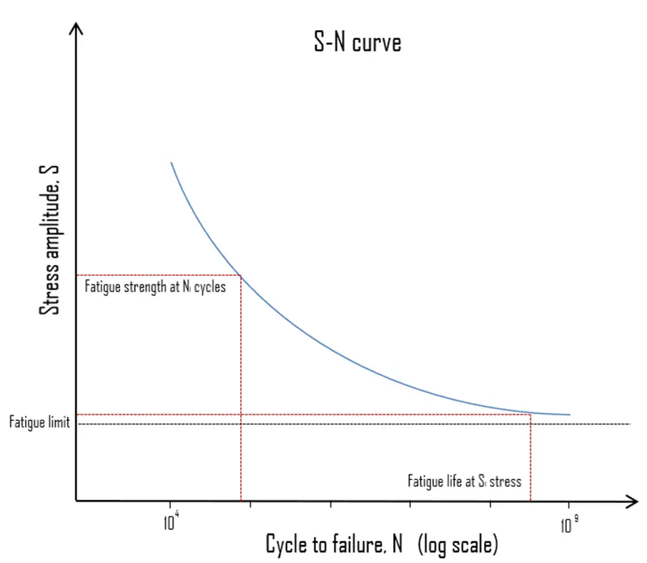
S-N curve - Fatigue Failure

The American Society for Testing and Materials defines fatigue life, Nf, as the number of stress cycles of a specified character that a specimen sustains before failure of a specified nature occurs. Fatigue life is affected by cyclic stresses, residual stresses, material properties, internal defects, grain size, temperature, design geometry, surface quality, oxidation, corrosion, etc. For some materials, notably steel and titanium, there is a theoretical value for stress amplitude below which the material will not fail for any number of cycles, called a fatigue limit, endurance limit, or fatigue strength.

Engineers use a number of methods to determine the fatigue life of a material. One of the most useful is the stress-life method, is commonly characterized by an S-N curve, also known as a Wöhler curve. This method is illustrated in the figure It plots applied stress (S) against component life or number of cycles to failure (N). As the stress decreases from some high value, component life increases slowly at first and then quite rapidly. Because fatigue like brittle fracture has such a variable nature, the data used to plot the curve will be treated statistically. The scatter in results is a consequence of the fatigue sensitivity to a number of test and material parameters that are impossible to control precisely.

The following terms are defined for S-N curve:

  • Fatigue Limit. Fatigue limit (also sometimes called the endurance limit) is the stress level, below which fatigue failure does not occur. This limit exists only for some ferrous (iron-base) and titanium alloys, for which the S–N curve becomes horizontal at higher N values. Other structural metals, such as aluminium and copper, do not have a distinct limit and will eventually fail even from small stress amplitudes. Typical values of the limit for steels are 1/2 the ultimate tensile strength, to a maximum of 290 MPa (42 ksi).
  • Fatigue Strength. The ASTM defines fatigue strength, SNf, as the value of stress at which failure occurs after some specified number of cycles (e.g., 107 cycles) For example, the fatigue strength for annealed Ti-6Al-4V titanium alloy is about 240 MPa at 107 cycles and the stress concentration factor = 3.3.
  • Fatigue Life. Fatigue life characterizes a material’s fatigue behavior. It is the number of cycles to cause failure at a specified stress level, as taken from the S–N plot

The process of fatigue failure is characterized by three distinct steps:

  • Crack initiation, in which a small crack forms at some point of high stress concentration.
  • Crack propagation, during which this crack advances incrementally with each stress cycle. Most of the fatigue life is generally consumed in the crack growth phase.
  • Ultimate failure, which occurs very rapidly once the advancing crack has reached a critical size.

Cracks associated with fatigue failure almost always initiate (or nucleate) on the surface of a component at some point of stress concentration. Anything which leads to stress concentration, and the development of cracks, will reduce fatigue life. Therefore, increasing the degree of surface finish, polishing as compared to grinding, improves fatigue life. Increasing the strength and hardness of the surface layers of metal components will also improve fatigue life.
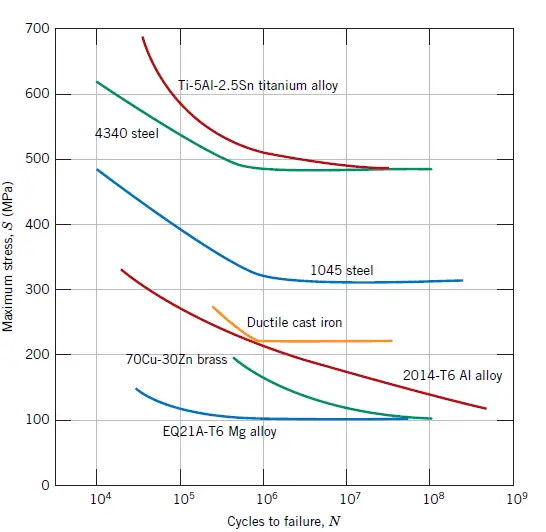
S-N curves of different materials
Maximum stress (S) versus logarithm of the number of cycles to fatigue failure (N) for seven metal alloys. Curves were generated using rotating–bending and reversed-cycle tests. Source: William D. Callister, David G. Rethwisch. Materials Science and Engineering: An Introduction 9th Edition, Wiley; 9 edition (December 4, 2013), ISBN-13: 978-1118324578.
References:

Materials Science:

  1. U.S. Department of Energy, Material Science. DOE Fundamentals Handbook, Volume 1 and 2. January 1993.
  2. U.S. Department of Energy, Material Science. DOE Fundamentals Handbook, Volume 2 and 2. January 1993.
  3. William D. Callister, David G. Rethwisch. Materials Science and Engineering: An Introduction 9th Edition, Wiley; 9 edition (December 4, 2013), ISBN-13: 978-1118324578.
  4. Eberhart, Mark (2003). Why Things Break: Understanding the World by the Way It Comes Apart. Harmony. ISBN 978-1-4000-4760-4.
  5. Gaskell, David R. (1995). Introduction to the thermodynamics of Materials (4th ed.). Taylor and Francis Publishing. ISBN 978-1-56032-992-3.
  6. González-Viñas, W. & Mancini, H.L. (2004). An Introduction to Materials Science. Princeton University Press. ISBN 978-0-691-07097-1.
  7. Ashby, Michael; Hugh Shercliff; David Cebon (2007). Materials: engineering, science, processing and design (1st ed.). Butterworth-Heinemann. ISBN 978-0-7506-8391-3.
  8. J. R. Lamarsh, A. J. Baratta, Introduction to Nuclear Engineering, 3d ed., Prentice-Hall, 2001, ISBN: 0-201-82498-1.

See above:
Failure Modes

We hope, this article, Fatigue of Material – Fatigue Failure, helps you. If so, give us a like in the sidebar. Main purpose of this website is to help the public to learn some interesting and important information about materials and their properties.

What is Uranium Silicide Fuel – Definition

Uranium silicide is an inorganic compound of uranium. It is one of possible designs of accident tolerant fuel pellet materials proposed. Advantages are higher percentage of uranium and higher thermal conductivity.

Most of PWRs use the uranium fuel, which is in the form of uranium dioxide. Uranium dioxide is a black semiconducting solid with very low thermal conductivity. On the other hand the uranium dioxide has very high melting point and has well known behavior. The UO2 is pressed into pellets, these pellets are then sintered into the solid cylinder (with a height, and diameter of about 1 centimeter, the height being greater than the diameter). The dimensions of the fuel pellets and other components of the fuel assembly are precisely controlled to ensure consistency in the characteristics of the fuel. These pellets are then loaded and encapsulated within a fuel rod (a metallic cladding tube), which is made of zirconium alloys due to its very low absorption cross-section (unlike the stainless steel). The surface of the tube, which covers the pellets, is called fuel cladding. Fuel rods are base element of a fuel assembly. Fuel rods have the purpose of containing fission products, ensuring mechanical support for the pellets, and allowing the heat removal to the coolant fluid of the heat generated by nuclear reactions. Typical fuel rod, has a length of some 4 m, with a diameter of around 1 cm. An 1100 MWe (3300 MWth) nuclear core may contain 157 fuel assemblies composed of over 45,000 fuel rods and some 15 million fuel pellets.

Advanced Fuel Pellets

 According to the NEA report, the fuel designs covered by the Task Force on Advanced Fuel Designs consist of three different concepts:

  • Improved UO2 fuel. Regarding the improved UO2 fuel, this particular design was divided into two sub-concepts, such as oxide-doped UO2 and high-thermal conductivity UO2 (designed by adding metallic or ceramic dopant).
  • High-density fuel.
  • Encapsulated fuel (TRISO-SiC-composite pellets).

Special Reference: Nuclear Energy Agency, State-of-the-Art Report on Light Water Reactor Accident-Tolerant Fuel. NEA No.7317, OECD, 2018.

High-density fuel

Most of the metallic materials suggested for use as cladding to reduce the steam oxidation present fairly large reactivity penalties compared to the traditional Zr-based claddings. These penalties can be compensated by either an increase of the 235U enrichment and/or a decrease in the cycle length. To compensate for this without the previous concessions, the fissile density in the pellet has to be increased. The fissile density can be increased in several ways. One possible way is to increase the density of the material, and another one is to increase the metal to non-metal ratio in the metal compound fuels.

There are sevaral proposed designs of high-density fuel, but it must be noted, all the high-density fuels are far from ready to be used as fuels in commercial light water reactors. The concepts include:

  • Nitride Fuels
  • Silicide Fuels
  • Carbide Fuels
  • Metallic Fuels

Uranium Silicide Fuel

Uranium silicide is an inorganic compound of uranium. It is one of possible designs of accident tolerant fuel pellet materials proposed. Advantages are higher percentage of uranium and higher thermal conductivity. With a density uranium silicide of 12.2 g/cm3 (vs. ), uranium silicide (U3Si2) offers a boost in fuel economics. Uranium dioxide has a density of 10.97 g/cm3. Moreover, there is a surplus from its stechiometric composition. In final, there is about 17% higher uranium density than that of uranium dioxide. A direct replacement of UO2 with U3Si2 should enable a reactor to generate more energy from a set of fuel rods and also provide more “coping time” in the case severe accidents. Its thermal conductivity (~8.5 W/m.K at 300 K) is significantly higher than that of uranium dioxide at operating temperatures, and it increases as a function of temperature (uranium dioxide’s thermal conductivity decreases as a function of temperature). This thermal conductivity offsets its lower melting point such that fuel operating and safety margins are improved.

Westinghouse, the Idaho National Laboratory (INL) and the Los Alamos National Laboratory began developing and manufacturing uranium silicide and its composite fuels through DOE’s Accident Tolerant Fuel programme. The improved thermal performance of U3Si2 compared to UO2 fuel allows implementation of a more advanced cladding such as a SiC-SiC-composite, which besides the expected operational and safety  benefits, also offers superior neutron economy and further fuel cycle cost savings relative to Zr-based claddings.

Encapsulated fuel – TRISO-SiC-composite pellets

TRISO
TRISO, TRI-structural ISO-tropic, is a type of micro fuel particle, which consists of fissile material-bearing kernels that are coated with multiple layers of porous or dense carbon and silicon carbide. Source: energy.gov License: Public Domain

TRISO, TRI-structural ISO-tropic, is a type of micro fuel particle, which consists of fissile material-bearing kernels that are coated with multiple layers of porous or dense carbon and silicon carbide. Historically, TRISO  particles have been utilized in fuel elements consisting of spherical pebbles or hexagonal prismatic blocks with graphite used as a matrix and coating for the fuel element. Each particle acts as its own containment system thanks to its triple-coated layers. This allows them to retain fission products under all reactor conditions. TRISO particles can withstand extreme temperatures that are well beyond the threshold of current nuclear fuels. TRISO-SiC-composite pellets consist of TRISO fuel particles embedded in an SiC matrix. Using SiC as a matrix instead of graphite improves the radiation tolerance of the fuel matrix while also enhancing FP retention. The TRISO-SiC-composite fuel is generally called a fully ceramic microencapsulated (FCM) fuel.

According to NEA report, the TRISO-SiC fuel is conceived as a promising medium-term concept to replace current UO2 fuel pellets. It has potentially superior safety characteristics relative to other fuel forms as a result of its multiple barriers to FP dispersion, high mechanical stability and good thermal conductivity. A low fissile material loading density is the major issue for this concept. In order to increase the fissile loading, the combination of uranium enrichment up to the practical upper limit of LEU(~19.7% of 235-U), increasing kernel-to-particle volume fraction and TRISO-packing fraction, and enlarging fuel pin diameter was proposed.

Silicon carbide is exceedingly hard, synthetically produced crystalline compound of silicon and carbon. Its chemical formula is SiC. Silicon carbide has a Mohs hardness rating of 9, approaching that of diamond. Its high thermal conductivity, together with its high-temperature strength, low thermal expansion, and resistance to chemical reaction, makes silicon carbide valuable in the manufacture of high-temperature applications and other refractories. In nuclear industry, silicon carbide composite material has been investigated for use as a replacement for zirconium alloy cladding in light water reactors. Silicon carbide (SiC) based ceramics and their composites have superior high-temperature (HT) properties, excellent irradiation resistance, inherent low activation and other superior physical/chemical properties.

References:
Materials Science:

U.S. Department of Energy, Material Science. DOE Fundamentals Handbook, Volume 1 and 2. January 1993.
U.S. Department of Energy, Material Science. DOE Fundamentals Handbook, Volume 2 and 2. January 1993.
William D. Callister, David G. Rethwisch. Materials Science and Engineering: An Introduction 9th Edition, Wiley; 9 edition (December 4, 2013), ISBN-13: 978-1118324578.
Eberhart, Mark (2003). Why Things Break: Understanding the World by the Way It Comes Apart. Harmony. ISBN 978-1-4000-4760-4.
Gaskell, David R. (1995). Introduction to the thermodynamics of Materials (4th ed.). Taylor and Francis Publishing. ISBN 978-1-56032-992-3.
González-Viñas, W. & Mancini, H.L. (2004). An Introduction to Materials Science. Princeton University Press. ISBN 978-0-691-07097-1.
Ashby, Michael; Hugh Shercliff; David Cebon (2007). Materials: engineering, science, processing and design (1st ed.). Butterworth-Heinemann. ISBN 978-0-7506-8391-3.
J. R. Lamarsh, A. J. Baratta, Introduction to Nuclear Engineering, 3d ed., Prentice-Hall, 2001, ISBN: 0-201-82498-1.

See above:
Accident Tolerant Fuel

We hope, this article, Uranium Silicide Fuel, helps you. If so, give us a like in the sidebar. Main purpose of this website is to help the public to learn some interesting and important information about materials and their properties.

What is Encapsulated fuel – TRISO-SiC-composite pellets – Definition

TRISO, TRI-structural ISO-tropic, is a type of micro fuel particle, which consists of fissile material-bearing kernels that are coated with multiple layers of porous or dense carbon and silicon carbide.

Most of PWRs use the uranium fuel, which is in the form of uranium dioxide. Uranium dioxide is a black semiconducting solid with very low thermal conductivity. On the other hand the uranium dioxide has very high melting point and has well known behavior. The UO2 is pressed into pellets, these pellets are then sintered into the solid cylinder (with a height, and diameter of about 1 centimeter, the height being greater than the diameter). The dimensions of the fuel pellets and other components of the fuel assembly are precisely controlled to ensure consistency in the characteristics of the fuel. These pellets are then loaded and encapsulated within a fuel rod (a metallic cladding tube), which is made of zirconium alloys due to its very low absorption cross-section (unlike the stainless steel). The surface of the tube, which covers the pellets, is called fuel cladding. Fuel rods are base element of a fuel assembly. Fuel rods have the purpose of containing fission products, ensuring mechanical support for the pellets, and allowing the heat removal to the coolant fluid of the heat generated by nuclear reactions. Typical fuel rod, has a length of some 4 m, with a diameter of around 1 cm. An 1100 MWe (3300 MWth) nuclear core may contain 157 fuel assemblies composed of over 45,000 fuel rods and some 15 million fuel pellets.

Encapsulated fuel – TRISO-SiC-composite pellets

TRISO
TRISO, TRI-structural ISO-tropic, is a type of micro fuel particle, which consists of fissile material-bearing kernels that are coated with multiple layers of porous or dense carbon and silicon carbide. Source: energy.gov License: Public Domain

TRISO, TRI-structural ISO-tropic, is a type of micro fuel particle, which consists of fissile material-bearing kernels that are coated with multiple layers of porous or dense carbon and silicon carbide. Historically, TRISO  particles have been utilized in fuel elements consisting of spherical pebbles or hexagonal prismatic blocks with graphite used as a matrix and coating for the fuel element. Each particle acts as its own containment system thanks to its triple-coated layers. This allows them to retain fission products under all reactor conditions. TRISO particles can withstand extreme temperatures that are well beyond the threshold of current nuclear fuels. TRISO-SiC-composite pellets consist of TRISO fuel particles embedded in an SiC matrix. Using SiC as a matrix instead of graphite improves the radiation tolerance of the fuel matrix while also enhancing FP retention. The TRISO-SiC-composite fuel is generally called a fully ceramic microencapsulated (FCM) fuel.

According to NEA report, the TRISO-SiC fuel is conceived as a promising medium-term concept to replace current UO2 fuel pellets. It has potentially superior safety characteristics relative to other fuel forms as a result of its multiple barriers to FP dispersion, high mechanical stability and good thermal conductivity. A low fissile material loading density is the major issue for this concept. In order to increase the fissile loading, the combination of uranium enrichment up to the practical upper limit of LEU(~19.7% of 235-U), increasing kernel-to-particle volume fraction and TRISO-packing fraction, and enlarging fuel pin diameter was proposed.

Silicon carbide is exceedingly hard, synthetically produced crystalline compound of silicon and carbon. Its chemical formula is SiC. Silicon carbide has a Mohs hardness rating of 9, approaching that of diamond. Its high thermal conductivity, together with its high-temperature strength, low thermal expansion, and resistance to chemical reaction, makes silicon carbide valuable in the manufacture of high-temperature applications and other refractories. In nuclear industry, silicon carbide composite material has been investigated for use as a replacement for zirconium alloy cladding in light water reactors. Silicon carbide (SiC) based ceramics and their composites have superior high-temperature (HT) properties, excellent irradiation resistance, inherent low activation and other superior physical/chemical properties.

References:
Materials Science:

U.S. Department of Energy, Material Science. DOE Fundamentals Handbook, Volume 1 and 2. January 1993.
U.S. Department of Energy, Material Science. DOE Fundamentals Handbook, Volume 2 and 2. January 1993.
William D. Callister, David G. Rethwisch. Materials Science and Engineering: An Introduction 9th Edition, Wiley; 9 edition (December 4, 2013), ISBN-13: 978-1118324578.
Eberhart, Mark (2003). Why Things Break: Understanding the World by the Way It Comes Apart. Harmony. ISBN 978-1-4000-4760-4.
Gaskell, David R. (1995). Introduction to the thermodynamics of Materials (4th ed.). Taylor and Francis Publishing. ISBN 978-1-56032-992-3.
González-Viñas, W. & Mancini, H.L. (2004). An Introduction to Materials Science. Princeton University Press. ISBN 978-0-691-07097-1.
Ashby, Michael; Hugh Shercliff; David Cebon (2007). Materials: engineering, science, processing and design (1st ed.). Butterworth-Heinemann. ISBN 978-0-7506-8391-3.
J. R. Lamarsh, A. J. Baratta, Introduction to Nuclear Engineering, 3d ed., Prentice-Hall, 2001, ISBN: 0-201-82498-1.

See above:
Accident Tolerant Fuel

We hope, this article, Encapsulated fuel – TRISO-SiC-composite pellets, helps you. If so, give us a like in the sidebar. Main purpose of this website is to help the public to learn some interesting and important information about materials and their properties.

What is Accident-tolerant control rods – ATCR – Definition

The following inherent characteristics are required in accident tolerant control rods: The reactivity worth of ATCR should be comparable to or exceed that of conventional CR.The neutron-absorbing materials used in ATCR should have sufficiently high melting point.

Control rods are an important safety system of nuclear reactors. Their prompt action and prompt response of the reactor is indispencable. Control rods are used for maintaining the desired state of fission reactions within a nuclear reactor (i.e. subcritical state, critical state, power changes) They constitute a key component of an emergency shutdown system (SCRAM).

Control rods are rods, plates, or tubes containing a neutron absorbing material (material with high absorbtion cross-section for thermal neutron) such as boron, hafnium, cadmium, etc., used to control the power of a nuclear reactor. By absorbing neutrons, a control rod prevents the neutrons from causing further fissions.

Control rods usually constitute cluster control rod assemblies (PWR) and are inserted into guide thimbles within a nuclear fuel assembly. The absorbing material (e.g. pellets of Boron Carbide or Ag-In-Cd alloy) is protected by the cladding usually made of stainless steel.

Neverthless, the melting point of Ag-In-Cd alloy (~790 ̊C), the eutectic temperature of boron carbide (B4C) and Fe (~1150 ̊C) and the eutectic temperature of Fe and Zr (~950 ̊C) are lower than the temperature (≳1 200) at which Zr-alloy fuel cladding begins to be intensively oxidised under severe accident conditions. Accordingly, it is possible that the control rods melt and collapse before the reactor core is significantly damaged in the case of severe accidents.

The following inherent characteristics are required in accident tolerant control rods:

  • The reactivity worth of ATCR should be comparable to or exceed that of conventional CR.
  • The neutron-absorbing materials used in ATCR should have sufficiently high melting point and high eutectic temperature with cladding to prevent breakage of the CRs prior to extensive fuel rod failure in a severe accident, thus avoiding uncontrollable recriticality even if unborated water is injected for emergency cooling of the core.

The main idea is to replace the conventional neutron-absorbing materials with proper ceramic materials that satisfy the above requirements. The candidate of a new absorber material for ATC includes gadolinia (Gd2O3), samaria (Sm2O3), europia (Eu2O3), dysprosia (Dy2O3), hafnia (HfO2). The melting point of these materials and the liquefaction temperature with Fe are higher than the rapid zirconium alloy oxidation temperature.

References:
Materials Science:

U.S. Department of Energy, Material Science. DOE Fundamentals Handbook, Volume 1 and 2. January 1993.
U.S. Department of Energy, Material Science. DOE Fundamentals Handbook, Volume 2 and 2. January 1993.
William D. Callister, David G. Rethwisch. Materials Science and Engineering: An Introduction 9th Edition, Wiley; 9 edition (December 4, 2013), ISBN-13: 978-1118324578.
Eberhart, Mark (2003). Why Things Break: Understanding the World by the Way It Comes Apart. Harmony. ISBN 978-1-4000-4760-4.
Gaskell, David R. (1995). Introduction to the thermodynamics of Materials (4th ed.). Taylor and Francis Publishing. ISBN 978-1-56032-992-3.
González-Viñas, W. & Mancini, H.L. (2004). An Introduction to Materials Science. Princeton University Press. ISBN 978-0-691-07097-1.
Ashby, Michael; Hugh Shercliff; David Cebon (2007). Materials: engineering, science, processing and design (1st ed.). Butterworth-Heinemann. ISBN 978-0-7506-8391-3.
J. R. Lamarsh, A. J. Baratta, Introduction to Nuclear Engineering, 3d ed., Prentice-Hall, 2001, ISBN: 0-201-82498-1.

See above:
Accident Tolerant Fuel

We hope, this article, Accident-tolerant control rods – ATCR, helps you. If so, give us a like in the sidebar. Main purpose of this website is to help the public to learn some interesting and important information about materials and their properties.

What is Improved UO2 fuel – Doped UO2 – Definition

Regarding the improved UO2 fuel, this particular design was divided into two sub-concepts, such as: Doped UO2. Desirable attributes for accident-tolerant fuel (ATF) pellets include enhancing the retention of fission products (FPs).

Most of PWRs use the uranium fuel, which is in the form of uranium dioxide. Uranium dioxide is a black semiconducting solid with very low thermal conductivity. On the other hand the uranium dioxide has very high melting point and has well known behavior. The UO2 is pressed into pellets, these pellets are then sintered into the solid cylinder (with a height, and diameter of about 1 centimeter, the height being greater than the diameter). The dimensions of the fuel pellets and other components of the fuel assembly are precisely controlled to ensure consistency in the characteristics of the fuel. These pellets are then loaded and encapsulated within a fuel rod (a metallic cladding tube), which is made of zirconium alloys due to its very low absorption cross-section (unlike the stainless steel). The surface of the tube, which covers the pellets, is called fuel cladding. Fuel rods are base element of a fuel assembly. Fuel rods have the purpose of containing fission products, ensuring mechanical support for the pellets, and allowing the heat removal to the coolant fluid of the heat generated by nuclear reactions. Typical fuel rod, has a length of some 4 m, with a diameter of around 1 cm. An 1100 MWe (3300 MWth) nuclear core may contain 157 fuel assemblies composed of over 45,000 fuel rods and some 15 million fuel pellets.

Advanced Fuel Pellets

 According to the NEA report, the fuel designs covered by the Task Force on Advanced Fuel Designs consist of three different concepts:

  • Improved UO2 fuel. Regarding the improved UO2 fuel, this particular design was divided into two sub-concepts, such as oxide-doped UO2 and high-thermal conductivity UO2 (designed by adding metallic or ceramic dopant).
  • High-density fuel.
  • Encapsulated fuel (TRISO-SiC-composite pellets).

Special Reference: Nuclear Energy Agency, State-of-the-Art Report on Light Water Reactor Accident-Tolerant Fuel. NEA No.7317, OECD, 2018.

Improved UO2 fuel

Most of PWRs use the uranium fuel, which is in the form of uranium dioxide. Uranium dioxide is a black semiconducting solid with very low thermal conductivity. On the other hand the uranium dioxide has very high melting point and has well known behavior. The UO2 is pressed into pellets, these pellets are then sintered into the solid cylinder (with a height, and diameter of about 1 centimeter, the height being greater than the diameter).

Regarding the improved UO2 fuel, this particular design was divided into two sub-concepts, such as:

  • Doped UO2.  Desirable attributes for accident-tolerant fuel (ATF) pellets include enhancing the retention of fission products (FPs) and  minimising  pellet-cladding  interaction.  According to Westinghouse proposals, chromia (Cr2O3) and alumina  (Al2O3) doped UO2 pellet, known as our ADOPT pellet, achieves greater uranium efficiency through:
    • Increased density of fissile material
    • A higher creep rate than standard UO2 at high temperatures
    • A higher thermal stability
    • Reduced wash-out in the event of a fuel rod leaker
    • Reduction of fission gas release in a transient scenario
  • High-thermal conductivity UO2 (designed by adding metallic or ceramic dopant). Uranium dioxide is a black semiconducting solid with very low thermal conductivity. The thermal conductivity is one of parameters, which determine the fuel centerline temperature. This low thermal conductivity can result in localised overheating in the fuel centerline and therefore this overheating must be avoided. The concept of cermet (ceramic-metallic) fuel for LWRs is considered. With a low volume  fraction of highly conductive metallic additive, the CERMET fuel pellets present a higher conductivity than UO2 standard pellets, lowering the fuel  temperature  in  normal operating conditions and increasing the margins with respect to fuel melting in case of an accident.
References:
Materials Science:

U.S. Department of Energy, Material Science. DOE Fundamentals Handbook, Volume 1 and 2. January 1993.
U.S. Department of Energy, Material Science. DOE Fundamentals Handbook, Volume 2 and 2. January 1993.
William D. Callister, David G. Rethwisch. Materials Science and Engineering: An Introduction 9th Edition, Wiley; 9 edition (December 4, 2013), ISBN-13: 978-1118324578.
Eberhart, Mark (2003). Why Things Break: Understanding the World by the Way It Comes Apart. Harmony. ISBN 978-1-4000-4760-4.
Gaskell, David R. (1995). Introduction to the thermodynamics of Materials (4th ed.). Taylor and Francis Publishing. ISBN 978-1-56032-992-3.
González-Viñas, W. & Mancini, H.L. (2004). An Introduction to Materials Science. Princeton University Press. ISBN 978-0-691-07097-1.
Ashby, Michael; Hugh Shercliff; David Cebon (2007). Materials: engineering, science, processing and design (1st ed.). Butterworth-Heinemann. ISBN 978-0-7506-8391-3.
J. R. Lamarsh, A. J. Baratta, Introduction to Nuclear Engineering, 3d ed., Prentice-Hall, 2001, ISBN: 0-201-82498-1.

See above:
Accident Tolerant Fuel

We hope, this article, Improved UO2 fuel – Doped UO2, helps you. If so, give us a like in the sidebar. Main purpose of this website is to help the public to learn some interesting and important information about materials and their properties.

What is Zr-alloy lined Molybdenum Cladding – Definition

The Zr-alloy lined Mo-cladding is anticipated to possess sufficient corrosion and hydriding resistance for the current fuel burnup limit and beyond. The fully metallic Mo–Zr and Mo–FeCrAl duplex claddings are anticipated to achieve accident tolerance by forming a protective oxide during an accident.

Accident tolerant fuels (ATF) are a series of new nuclear fuel concepts, researched in order to improve fuel performance during normal operation, transient conditions, and accident scenarios, such as loss-of-coolant accident (LOCA) or reactivity-initiated accidents (RIA). Following the Fukushima Daiichi accident, a review of fuel behaviour has been initiated. Zirconium alloy clad fuel operates successfully to high burnup and is the result of 40 years of continuous development and improvement. However, under severe accident conditions, the high temperature zirconium–steam interaction can be a major source of damage to the power plant.

These upgrades include:

  • specially designed additives to standard fuel pellets intended to improve various properties and performance
  • robust coatings applied to the outside of standard claddings intended to reduce corrosion, increase wear resistance, and reduce the production of hydrogen under high-temperature (accident) conditions
  • development of completely new fuel designs with ceramic cladding and different fuel materials

Current fuel cladding is the outer layer of the fuel rods, standing between the reactor coolant and the nuclear fuel (i.e. fuel pellets). It is made of a corrosion-resistant material with low absorption cross section for thermal neutrons (~ 0.18 × 10⁻²⁴ cm2), usually zirconium alloy. It prevents radioactive fission products from escaping the fuel matrix into the reactor coolant and contaminating it. Cladding constitute one of barriers in ‘defence-in-depth‘ approach, therefore its coolability is one of key safety aspects.

Special Reference: Nuclear Energy Agency, State-of-the-Art Report on Light Water Reactor Accident-Tolerant Fuel. NEA No.7317, OECD, 2018.

Refractory Metals for Fuel Cladding

Refractory metals and alloys are well known for their extraordinary resistance to heat and wear. Key requirement to withstand high temperatures is a high melting point and stable mechanical properties (e.g. high hardness) even at high temperatures. The most common refractory metals include five elements: niobium and molybdenum of the fifth period and tantalum, tungsten, and rhenium of the sixth period. They all share some properties, including a melting point above 2000 °C and high hardness at room temperature. Poor low-temperature fabricability and extreme oxidability at high temperatures are main disadvantages of most refractory metals. Application of these metals requires a protective atmosphere or coating.

Zr-alloy lined Molybdenum Cladding

In 2012, EPRI initiated an independent research project with conceptual designs of coated molybdenum alloy as an ATF cladding to achieve accident resistance to a temperature range of 1,200–1,500°C. Molybdenum (Mo) is a candidate because of its very high melting point (2623°C) and its high strength at elevated temperatures. At the same time, Mo and its alloys are known to be susceptible to the formation of volatile MoO3 in oxidizing environments at temperatures > 600°C. Therefore, this research programme uses a composite design in which the Mo alloy cladding is covered with an outer protective coating of either a Zr-alloy or an Al-containing alloy.

The Zr-alloy lined Mo-cladding is anticipated to possess sufficient corrosion and hydriding resistance for the current fuel burnup limit and beyond. The fully metallic Mo–Zr and Mo–FeCrAl duplex claddings are anticipated to achieve accident tolerance by forming a protective oxide during an accident. The thin Zr-alloy coating will be completely oxidized to ZrO2 as the temperature reaches 1,000°C or higher. With proper alloying, the ZrO2 will maintain its integrity and stability and provide protection to the underlining Mo-alloy. A thin FeCrAl coating is highly corrosion resistant in LWR coolants due to formation of a chromium-rich protective oxide, mainly Cr2O3. In high temperature steam, FeCrAl is highly corrosion resistant due to the formation of a thin aluminum rich oxide, Al2O3. FeCrAl alloys consist of mainly iron, chromium (20–30%) and aluminium (4–7.5 %). These alloys are known under the trademark Kanthal, which is a family of iron-chromium-aluminium (FeCrAl) alloys used in a wide range of resistance and high-temperature applications.

Molybdenum is highly resistant to oxidation in high-purity or reducing steam. Therefore, the lined molybdenum-cladding is anticipated to maintain good integrity in the event of steam ingress into a failed fuel rod, as well as under a design-basis LOCA. In the event the outer coating is locally removed, such as due to grid-to-rod fretting, localised corrosion of molybdenum cladding may occur.

References:
Materials Science:

U.S. Department of Energy, Material Science. DOE Fundamentals Handbook, Volume 1 and 2. January 1993.
U.S. Department of Energy, Material Science. DOE Fundamentals Handbook, Volume 2 and 2. January 1993.
William D. Callister, David G. Rethwisch. Materials Science and Engineering: An Introduction 9th Edition, Wiley; 9 edition (December 4, 2013), ISBN-13: 978-1118324578.
Eberhart, Mark (2003). Why Things Break: Understanding the World by the Way It Comes Apart. Harmony. ISBN 978-1-4000-4760-4.
Gaskell, David R. (1995). Introduction to the thermodynamics of Materials (4th ed.). Taylor and Francis Publishing. ISBN 978-1-56032-992-3.
González-Viñas, W. & Mancini, H.L. (2004). An Introduction to Materials Science. Princeton University Press. ISBN 978-0-691-07097-1.
Ashby, Michael; Hugh Shercliff; David Cebon (2007). Materials: engineering, science, processing and design (1st ed.). Butterworth-Heinemann. ISBN 978-0-7506-8391-3.
J. R. Lamarsh, A. J. Baratta, Introduction to Nuclear Engineering, 3d ed., Prentice-Hall, 2001, ISBN: 0-201-82498-1.

See above:
Accident Tolerant Fuel

We hope, this article, Zr-alloy lined Molybdenum Cladding, helps you. If so, give us a like in the sidebar. Main purpose of this website is to help the public to learn some interesting and important information about materials and their properties.

What is SiC and SiC/SiC-composite claddings – Definition

SiC cladding is intended to provide groundbreaking safety margin improvements. SiC cladding reacts reacts many orders of magnitude slower with water and steam than zirconium at critical temperatures (above 800°C).

Accident tolerant fuels (ATF) are a series of new nuclear fuel concepts, researched in order to improve fuel performance during normal operation, transient conditions, and accident scenarios, such as loss-of-coolant accident (LOCA) or reactivity-initiated accidents (RIA). Following the Fukushima Daiichi accident, a review of fuel behaviour has been initiated. Zirconium alloy clad fuel operates successfully to high burnup and is the result of 40 years of continuous development and improvement. However, under severe accident conditions, the high temperature zirconium–steam interaction can be a major source of damage to the power plant.

These upgrades include:

  • specially designed additives to standard fuel pellets intended to improve various properties and performance
  • robust coatings applied to the outside of standard claddings intended to reduce corrosion, increase wear resistance, and reduce the production of hydrogen under high-temperature (accident) conditions
  • development of completely new fuel designs with ceramic cladding and different fuel materials

Current fuel cladding is the outer layer of the fuel rods, standing between the reactor coolant and the nuclear fuel (i.e. fuel pellets). It is made of a corrosion-resistant material with low absorption cross section for thermal neutrons (~ 0.18 × 10⁻²⁴ cm2), usually zirconium alloy. It prevents radioactive fission products from escaping the fuel matrix into the reactor coolant and contaminating it. Cladding constitute one of barriers in ‘defence-in-depth‘ approach, therefore its coolability is one of key safety aspects.

Special Reference: Nuclear Energy Agency, State-of-the-Art Report on Light Water Reactor Accident-Tolerant Fuel. NEA No.7317, OECD, 2018.

SiC and SiC/SiC-composite claddings

Silicon carbide is exceedingly hard, synthetically produced crystalline compound of silicon and carbon. Its chemical formula is SiC. Silicon carbide has a Mohs hardness rating of 9, approaching that of diamond. In addition to hardness, silicon carbide crystals have fracture characteristics that make them extremely useful in grinding wheels. Its high thermal conductivity, together with its high-temperature strength, low thermal expansion, and resistance to chemical reaction, makes silicon carbide valuable in the manufacture of high-temperature applications and other refractories.

In nuclear industry, silicon carbide composite material has been investigated for use as a replacement for zirconium alloy cladding in light water reactors. Silicon carbide (SiC) based ceramics and their composites have superior high-temperature (HT) properties, excellent irradiation resistance, inherent low activation and other superior physical/chemical properties. The composite consists of SiC fibers wrapped around a SiC inner layer and surrounded by an SiC outer layer. Problems have been reported with the ability to join the pieces of the SiC composite.

SiC cladding is intended to provide groundbreaking safety margin improvements. SiC cladding reacts reacts many orders of magnitude slower with water and steam than zirconium at critical temperatures (above 800°C), resulting in minimal generation of heat and hydrogen in beyond-design-basis accident scenarios. The SiC-composite claddings and fuel components are expected to provide excellent passive safety features both in design-basis accidents and design extension conditions severe accidents (SAs). Moreover, the SiC/SiC composites are anticipated to provide additional benefits over the Zr-alloys such as a reduced neutron absorption cross-section enabling a smaller uranium enrichment. The combination of these attractive features makes the SiC composites one of the leading candidates for accident-tolerant LWR fuel cladding and core structures.

There are three main disadvantages of the SiC/SiC composite fuel clads:

  • Fabrication. Fabrication of thin fuel clad requires further development. A technology for end-plug joining with gas tightness and adequate strength should be also developed  because the SiC ceramics cannot be welded.
  • Tritium releases. There is a potential increase in tritium release into the reactor coolant. Tritium is produced as a fission product (FP). SiC does not react with hydrogen to form stable hydrides similarly to a zirconium-based alloy, resulting in higher permeability of tritium through the cladding to the reactor coolant. The choice of using a proper liner material could help mitigate this issue.
  • SiC/SiC has significantly lower thermal conductivity than zirconium alloys. This fact negatively infuences pellet centerline temperatures and also the coping time.

One of possible SiC composite claddings has been developed by General Atomics and is known as SiGA™ silicon-carbide (SiC) composite, in which the SiC matrix material is reinforced with flexible SiC fiber in much the same way that steel rebar reinforces concrete. This creates an extremely hard and durable material that can withstand the harshest reactor conditions.

References:
Materials Science:

U.S. Department of Energy, Material Science. DOE Fundamentals Handbook, Volume 1 and 2. January 1993.
U.S. Department of Energy, Material Science. DOE Fundamentals Handbook, Volume 2 and 2. January 1993.
William D. Callister, David G. Rethwisch. Materials Science and Engineering: An Introduction 9th Edition, Wiley; 9 edition (December 4, 2013), ISBN-13: 978-1118324578.
Eberhart, Mark (2003). Why Things Break: Understanding the World by the Way It Comes Apart. Harmony. ISBN 978-1-4000-4760-4.
Gaskell, David R. (1995). Introduction to the thermodynamics of Materials (4th ed.). Taylor and Francis Publishing. ISBN 978-1-56032-992-3.
González-Viñas, W. & Mancini, H.L. (2004). An Introduction to Materials Science. Princeton University Press. ISBN 978-0-691-07097-1.
Ashby, Michael; Hugh Shercliff; David Cebon (2007). Materials: engineering, science, processing and design (1st ed.). Butterworth-Heinemann. ISBN 978-0-7506-8391-3.
J. R. Lamarsh, A. J. Baratta, Introduction to Nuclear Engineering, 3d ed., Prentice-Hall, 2001, ISBN: 0-201-82498-1.

See above:
Accident Tolerant Fuel

We hope, this article, SiC and SiC/SiC-composite claddings, helps you. If so, give us a like in the sidebar. Main purpose of this website is to help the public to learn some interesting and important information about materials and their properties.

What is Ceramic-coated Fuel Cladding – Definition

Ceramic coatings including oxides, carbides, and nitrides, and composite or multilayer coatings. Nitride ceramic coatings are used to harden materials and improve their wear behaviour, especially TiN and TiAlN.

Accident tolerant fuels (ATF) are a series of new nuclear fuel concepts, researched in order to improve fuel performance during normal operation, transient conditions, and accident scenarios, such as loss-of-coolant accident (LOCA) or reactivity-initiated accidents (RIA). Following the Fukushima Daiichi accident, a review of fuel behaviour has been initiated. Zirconium alloy clad fuel operates successfully to high burnup and is the result of 40 years of continuous development and improvement. However, under severe accident conditions, the high temperature zirconium–steam interaction can be a major source of damage to the power plant.

These upgrades include:

  • specially designed additives to standard fuel pellets intended to improve various properties and performance
  • robust coatings applied to the outside of standard claddings intended to reduce corrosion, increase wear resistance, and reduce the production of hydrogen under high-temperature (accident) conditions
  • development of completely new fuel designs with ceramic cladding and different fuel materials

Current fuel cladding is the outer layer of the fuel rods, standing between the reactor coolant and the nuclear fuel (i.e. fuel pellets). It is made of a corrosion-resistant material with low absorption cross section for thermal neutrons (~ 0.18 × 10⁻²⁴ cm2), usually zirconium alloy. It prevents radioactive fission products from escaping the fuel matrix into the reactor coolant and contaminating it. Cladding constitute one of barriers in ‘defence-in-depth‘ approach, therefore its coolability is one of key safety aspects.

Special Reference: Nuclear Energy Agency, State-of-the-Art Report on Light Water Reactor Accident-Tolerant Fuel. NEA No.7317, OECD, 2018.

Ceramic-coated Fuel Cladding

Ceramic coatings including oxides, carbides, and nitrides, and composite or multilayer coatings. Nitride ceramic coatings are used to harden materials and improve their wear behaviour, especially TiN and TiAlN. Additionally, CrN is also used for corrosion protection. Ceramic coatings are much more brittle than metallic coatings and thus more likely to undergo cracking and damage. One of main dissadvantages of ceramic coatings is the dissolution of Al-containing coatings (TiAlN, CrAlN, and to a significantly lower extent FeCrAl).

References:
Materials Science:

U.S. Department of Energy, Material Science. DOE Fundamentals Handbook, Volume 1 and 2. January 1993.
U.S. Department of Energy, Material Science. DOE Fundamentals Handbook, Volume 2 and 2. January 1993.
William D. Callister, David G. Rethwisch. Materials Science and Engineering: An Introduction 9th Edition, Wiley; 9 edition (December 4, 2013), ISBN-13: 978-1118324578.
Eberhart, Mark (2003). Why Things Break: Understanding the World by the Way It Comes Apart. Harmony. ISBN 978-1-4000-4760-4.
Gaskell, David R. (1995). Introduction to the thermodynamics of Materials (4th ed.). Taylor and Francis Publishing. ISBN 978-1-56032-992-3.
González-Viñas, W. & Mancini, H.L. (2004). An Introduction to Materials Science. Princeton University Press. ISBN 978-0-691-07097-1.
Ashby, Michael; Hugh Shercliff; David Cebon (2007). Materials: engineering, science, processing and design (1st ed.). Butterworth-Heinemann. ISBN 978-0-7506-8391-3.
J. R. Lamarsh, A. J. Baratta, Introduction to Nuclear Engineering, 3d ed., Prentice-Hall, 2001, ISBN: 0-201-82498-1.

See above:
Accident Tolerant Fuel

We hope, this article, Ceramic-coated Fuel Cladding, helps you. If so, give us a like in the sidebar. Main purpose of this website is to help the public to learn some interesting and important information about materials and their properties.

What are Advanced Steels – FeCrAl Fuel Clad – Definition

FeCrAl-based ATF utilises an FeCrAl alloy material as fuel rod cladding in combination with uranium dioxide fuel pellets currently in use. FeCrAl alloy clad fuel rods appear to exhibit properties that meet or exceed current fuel design technical requirements while providing increased safety benefit during design-basis events and severe accident conditions.

Accident tolerant fuels (ATF) are a series of new nuclear fuel concepts, researched in order to improve fuel performance during normal operation, transient conditions, and accident scenarios, such as loss-of-coolant accident (LOCA) or reactivity-initiated accidents (RIA). Following the Fukushima Daiichi accident, a review of fuel behaviour has been initiated. Zirconium alloy clad fuel operates successfully to high burnup and is the result of 40 years of continuous development and improvement. However, under severe accident conditions, the high temperature zirconium–steam interaction can be a major source of damage to the power plant.

These upgrades include:

  • specially designed additives to standard fuel pellets intended to improve various properties and performance
  • robust coatings applied to the outside of standard claddings intended to reduce corrosion, increase wear resistance, and reduce the production of hydrogen under high-temperature (accident) conditions
  • development of completely new fuel designs with ceramic cladding and different fuel materials

Current fuel cladding is the outer layer of the fuel rods, standing between the reactor coolant and the nuclear fuel (i.e. fuel pellets). It is made of a corrosion-resistant material with low absorption cross section for thermal neutrons (~ 0.18 × 10⁻²⁴ cm2), usually zirconium alloy. It prevents radioactive fission products from escaping the fuel matrix into the reactor coolant and contaminating it. Cladding constitute one of barriers in ‘defence-in-depth‘ approach, therefore its coolability is one of key safety aspects.

Special Reference: Nuclear Energy Agency, State-of-the-Art Report on Light Water Reactor Accident-Tolerant Fuel. NEA No.7317, OECD, 2018.

Advanced Steels

FeCrAl alloys consist of mainly iron, chromium (20–30%) and aluminium (4–7.5 %). These alloys are known under the trademark Kanthal, which is a family of iron-chromium-aluminium (FeCrAl) alloys used in a wide range of resistance and high-temperature applications. FeCrAl is highly corrosion resistant due to the formation of a thin aluminum rich oxide, Al2O3.

FeCrAl-based ATF utilises an FeCrAl alloy material as fuel rod cladding in combination with uranium dioxide (UO2) fuel pellets currently in use. FeCrAl alloy clad fuel rods (with UO2 fuel) appear to exhibit properties that meet or exceed current fuel design technical requirements (with the exceptions noted below) while providing increased safety benefit during design-basis events and severe accident conditions. The concept’s key advantage over Zircaloy is its substantially slower oxidation kinetics up to 1773 K (1500°C). FeCrAl alloys have mechanical strength similar or superior to that of zircaloy, with plastic yielding (ballooning) and perforation characteristics similar or better than zirconium alloys.

There are two main disadvantages of FeCrAl-based fuel clads:

  • Increased parasitic neutron absorption. Due to increased neutron absorption cross-section of iron.
  • Tritium releases. There is a potential increase in tritium release into the reactor coolant. Tritium is produced as a fission product (FP). FeCrAl does not react with hydrogen to form stable hydrides similarly to a zirconium-based alloy, resulting in higher permeability of tritium through the cladding to the reactor coolant.
References:
Materials Science:

U.S. Department of Energy, Material Science. DOE Fundamentals Handbook, Volume 1 and 2. January 1993.
U.S. Department of Energy, Material Science. DOE Fundamentals Handbook, Volume 2 and 2. January 1993.
William D. Callister, David G. Rethwisch. Materials Science and Engineering: An Introduction 9th Edition, Wiley; 9 edition (December 4, 2013), ISBN-13: 978-1118324578.
Eberhart, Mark (2003). Why Things Break: Understanding the World by the Way It Comes Apart. Harmony. ISBN 978-1-4000-4760-4.
Gaskell, David R. (1995). Introduction to the thermodynamics of Materials (4th ed.). Taylor and Francis Publishing. ISBN 978-1-56032-992-3.
González-Viñas, W. & Mancini, H.L. (2004). An Introduction to Materials Science. Princeton University Press. ISBN 978-0-691-07097-1.
Ashby, Michael; Hugh Shercliff; David Cebon (2007). Materials: engineering, science, processing and design (1st ed.). Butterworth-Heinemann. ISBN 978-0-7506-8391-3.
J. R. Lamarsh, A. J. Baratta, Introduction to Nuclear Engineering, 3d ed., Prentice-Hall, 2001, ISBN: 0-201-82498-1.

See above:
Accident Tolerant Fuel

We hope, this article, Advanced Steels – FeCrAl Fuel Clad, helps you. If so, give us a like in the sidebar. Main purpose of this website is to help the public to learn some interesting and important information about materials and their properties.

What are Advanced Fuel Pellets – Definition

According to the NEA report, the fuel designs covered by the Task Force on Advanced Fuel Designs consist of three different concepts: Improved UO2 fuel, high-density fuel, encapsulated fuel. Advanced Fuel Pellets

Most of PWRs use the uranium fuel, which is in the form of uranium dioxide. Uranium dioxide is a black semiconducting solid with very low thermal conductivity. On the other hand the uranium dioxide has very high melting point and has well known behavior. The UO2 is pressed into pellets, these pellets are then sintered into the solid cylinder (with a height, and diameter of about 1 centimeter, the height being greater than the diameter). The dimensions of the fuel pellets and other components of the fuel assembly are precisely controlled to ensure consistency in the characteristics of the fuel. These pellets are then loaded and encapsulated within a fuel rod (a metallic cladding tube), which is made of zirconium alloys due to its very low absorption cross-section (unlike the stainless steel). The surface of the tube, which covers the pellets, is called fuel cladding. Fuel rods are base element of a fuel assembly. Fuel rods have the purpose of containing fission products, ensuring mechanical support for the pellets, and allowing the heat removal to the coolant fluid of the heat generated by nuclear reactions. Typical fuel rod, has a length of some 4 m, with a diameter of around 1 cm. An 1100 MWe (3300 MWth) nuclear core may contain 157 fuel assemblies composed of over 45,000 fuel rods and some 15 million fuel pellets.

Advanced Fuel Pellets

 According to the NEA report, the fuel designs covered by the Task Force on Advanced Fuel Designs consist of three different concepts:

  • Improved UO2 fuel. Regarding the improved UO2 fuel, this particular design was divided into two sub-concepts, such as oxide-doped UO2 and high-thermal conductivity UO2 (designed by adding metallic or ceramic dopant).
  • High-density fuel.
  • Encapsulated fuel (TRISO-SiC-composite pellets).

Special Reference: Nuclear Energy Agency, State-of-the-Art Report on Light Water Reactor Accident-Tolerant Fuel. NEA No.7317, OECD, 2018.

Improved UO2 fuel

Most of PWRs use the uranium fuel, which is in the form of uranium dioxide. Uranium dioxide is a black semiconducting solid with very low thermal conductivity. On the other hand the uranium dioxide has very high melting point and has well known behavior. The UO2 is pressed into pellets, these pellets are then sintered into the solid cylinder (with a height, and diameter of about 1 centimeter, the height being greater than the diameter).

Regarding the improved UO2 fuel, this particular design was divided into two sub-concepts, such as:

  • Doped UO2.  Desirable attributes for accident-tolerant fuel (ATF) pellets include enhancing the retention of fission products (FPs) and  minimising  pellet-cladding  interaction.  According to Westinghouse proposals, chromia (Cr2O3) and alumina  (Al2O3) doped UO2 pellet, known as our ADOPT pellet, achieves greater uranium efficiency through:
    • Increased density of fissile material
    • A higher creep rate than standard UO2 at high temperatures
    • A higher thermal stability
    • Reduced wash-out in the event of a fuel rod leaker
    • Reduction of fission gas release in a transient scenario
  • High-thermal conductivity UO2 (designed by adding metallic or ceramic dopant). Uranium dioxide is a black semiconducting solid with very low thermal conductivity. The thermal conductivity is one of parameters, which determine the fuel centerline temperature. This low thermal conductivity can result in localised overheating in the fuel centerline and therefore this overheating must be avoided. The concept of cermet (ceramic-metallic) fuel for LWRs is considered. With a low volume  fraction of highly conductive metallic additive, the CERMET fuel pellets present a higher conductivity than UO2 standard pellets, lowering the fuel  temperature  in  normal operating conditions and increasing the margins with respect to fuel melting in case of an accident.

High-density fuel

Most of the metallic materials suggested for use as cladding to reduce the steam oxidation present fairly large reactivity penalties compared to the traditional Zr-based claddings. These penalties can be compensated by either an increase of the 235U enrichment and/or a decrease in the cycle length. To compensate for this without the previous concessions, the fissile density in the pellet has to be increased. The fissile density can be increased in several ways. One possible way is to increase the density of the material, and another one is to increase the metal to non-metal ratio in the metal compound fuels.

There are sevaral proposed designs of high-density fuel, but it must be noted, all the high-density fuels are far from ready to be used as fuels in commercial light water reactors. The concepts include:

  • Nitride Fuels
  • Silicide Fuels
  • Carbide Fuels
  • Metallic Fuels

Uranium Silicide Fuel

Uranium silicide is an inorganic compound of uranium. It is one of possible designs of accident tolerant fuel pellet materials proposed. Advantages are higher percentage of uranium and higher thermal conductivity. With a density uranium silicide of 12.2 g/cm3 (vs. ), uranium silicide (U3Si2) offers a boost in fuel economics. Uranium dioxide has a density of 10.97 g/cm3. Moreover, there is a surplus from its stechiometric composition. In final, there is about 17% higher uranium density than that of uranium dioxide. A direct replacement of UO2 with U3Si2 should enable a reactor to generate more energy from a set of fuel rods and also provide more “coping time” in the case severe accidents. Its thermal conductivity (~8.5 W/m.K at 300 K) is significantly higher than that of uranium dioxide at operating temperatures, and it increases as a function of temperature (uranium dioxide’s thermal conductivity decreases as a function of temperature). This thermal conductivity offsets its lower melting point such that fuel operating and safety margins are improved.

Westinghouse, the Idaho National Laboratory (INL) and the Los Alamos National Laboratory began developing and manufacturing uranium silicide and its composite fuels through DOE’s Accident Tolerant Fuel programme. The improved thermal performance of U3Si2 compared to UO2 fuel allows implementation of a more advanced cladding such as a SiC-SiC-composite, which besides the expected operational and safety  benefits, also offers superior neutron economy and further fuel cycle cost savings relative to Zr-based claddings.

Encapsulated fuel – TRISO-SiC-composite pellets

TRISO
TRISO, TRI-structural ISO-tropic, is a type of micro fuel particle, which consists of fissile material-bearing kernels that are coated with multiple layers of porous or dense carbon and silicon carbide. Source: energy.gov License: Public Domain

TRISO, TRI-structural ISO-tropic, is a type of micro fuel particle, which consists of fissile material-bearing kernels that are coated with multiple layers of porous or dense carbon and silicon carbide. Historically, TRISO  particles have been utilized in fuel elements consisting of spherical pebbles or hexagonal prismatic blocks with graphite used as a matrix and coating for the fuel element. Each particle acts as its own containment system thanks to its triple-coated layers. This allows them to retain fission products under all reactor conditions. TRISO particles can withstand extreme temperatures that are well beyond the threshold of current nuclear fuels. TRISO-SiC-composite pellets consist of TRISO fuel particles embedded in an SiC matrix. Using SiC as a matrix instead of graphite improves the radiation tolerance of the fuel matrix while also enhancing FP retention. The TRISO-SiC-composite fuel is generally called a fully ceramic microencapsulated (FCM) fuel.

According to NEA report, the TRISO-SiC fuel is conceived as a promising medium-term concept to replace current UO2 fuel pellets. It has potentially superior safety characteristics relative to other fuel forms as a result of its multiple barriers to FP dispersion, high mechanical stability and good thermal conductivity. A low fissile material loading density is the major issue for this concept. In order to increase the fissile loading, the combination of uranium enrichment up to the practical upper limit of LEU(~19.7% of 235-U), increasing kernel-to-particle volume fraction and TRISO-packing fraction, and enlarging fuel pin diameter was proposed.

Silicon carbide is exceedingly hard, synthetically produced crystalline compound of silicon and carbon. Its chemical formula is SiC. Silicon carbide has a Mohs hardness rating of 9, approaching that of diamond. Its high thermal conductivity, together with its high-temperature strength, low thermal expansion, and resistance to chemical reaction, makes silicon carbide valuable in the manufacture of high-temperature applications and other refractories. In nuclear industry, silicon carbide composite material has been investigated for use as a replacement for zirconium alloy cladding in light water reactors. Silicon carbide (SiC) based ceramics and their composites have superior high-temperature (HT) properties, excellent irradiation resistance, inherent low activation and other superior physical/chemical properties.

References:
Materials Science:

U.S. Department of Energy, Material Science. DOE Fundamentals Handbook, Volume 1 and 2. January 1993.
U.S. Department of Energy, Material Science. DOE Fundamentals Handbook, Volume 2 and 2. January 1993.
William D. Callister, David G. Rethwisch. Materials Science and Engineering: An Introduction 9th Edition, Wiley; 9 edition (December 4, 2013), ISBN-13: 978-1118324578.
Eberhart, Mark (2003). Why Things Break: Understanding the World by the Way It Comes Apart. Harmony. ISBN 978-1-4000-4760-4.
Gaskell, David R. (1995). Introduction to the thermodynamics of Materials (4th ed.). Taylor and Francis Publishing. ISBN 978-1-56032-992-3.
González-Viñas, W. & Mancini, H.L. (2004). An Introduction to Materials Science. Princeton University Press. ISBN 978-0-691-07097-1.
Ashby, Michael; Hugh Shercliff; David Cebon (2007). Materials: engineering, science, processing and design (1st ed.). Butterworth-Heinemann. ISBN 978-0-7506-8391-3.
J. R. Lamarsh, A. J. Baratta, Introduction to Nuclear Engineering, 3d ed., Prentice-Hall, 2001, ISBN: 0-201-82498-1.

See above:
Accident Tolerant Fuel

We hope, this article, Advanced Fuel Pellets, helps you. If so, give us a like in the sidebar. Main purpose of this website is to help the public to learn some interesting and important information about materials and their properties.