Facebook Instagram Youtube Twitter

What is Powder Metallurgy – Definition

Powder metallurgy (PM) is a growing and rappidly evolving branch of metallurgy based on the production of materials in the form of metal powders and the manufacturing of parts from these materials.

Powder metallurgy (PM) is a growing and rappidly evolving branch of metallurgy based on the production of materials in the form of metal powders and the manufacturing of parts from these materials. Powder metallurgy processes can avoid, or greatly reduce, the need to use metal removal processes, thereby drastically reducing yield losses in manufacture and often resulting in lower costs. The primary market for metal powder is for complex parts manufactured by various PM technologies.

Powder metallurgy is also used to make unique materials impossible to get from melting or forming in other ways. For example, tungsten carbide (WC), which is used extensively in mining in top hammer rock drill bits, downhole hammers, and many more applications, is made by powder metallurgy.

Powders of metals and alloys also are fabricated into parts for several reasons. Most importantly, parts of complex shapes, close tolerances, controlled density, and controlled (and often unusual) properties can be produced by PM methods. The high precision forming capability of PM generates components with near net shape, intricate features and good dimensional precision pieces are often finished without the need of machining. The most common method of PM part production is the two-step process of:

  • Powder compaction (by pressing). The powder is mixed at desired elemental ratios for the resulting alloy, and a binder is added to aid in the flowability of the powder in the forming process. The formulated powder is compacted to bring the powder particles in close proximity to encourage bonding. Compaction of the metal powders is performed in a rigid die under high pressure (typically around 135 to 680 Mpa). The compacted mass of powders is referred to as a green (unsintered) compact.
  • Sintering.  After compaction of a green compact, powdered materials are heated in a controlled atmosphere in a process known as sintering. During sintering, compacted metal powders are bonded or sintered by heating in a furnace to a temperature that is usually below the melting point of the major constituent. Sintering of powder metals is a process in which particles under pressure chemically bond to themselves in order to form a coherent shape when exposed to a high temperature. This process is known as solid-state sintering. If the temperature is above the melting point of a component in the powder metal part, the liquid of the melted particles fills the pores. This type of sintering is known as liquid-state sintering. Sintering time and temperature are the most significant factors from a practical perspective, with temperature being the most important variable. During this process, a number of characteristics are increased including the strength, ductility, toughness, and electrical and thermal conductivity of the material. If different elemental powders are compact and sintered, the material would form into alloys and intermetallic phases.

There are also other methods of powder compaction such as metal injection molding and high-temperature compaction techniques (such as hot isostatic pressing and powder forging) that consolidate metal powders to higher densities approaching or equaling that of wrought products.

Fabrication of parts by PM methods has several advantages that include:

  • Producing parts with more uniform microstructure and distribution of alloying elements. Products are more predictable in their behaviour across a wide range of applications.
  • The high precision forming capability of allows for production of parts with netshape or near-net-shape dimensions (thus reducing the need for machining)
  • Flexibility in component design
  • Some spacial materials (e.g. very hard materials) can be produced only by powder metallurgy

Main disadvantages of powder metallurgy lies in high cost of metal powders compared to the cost of raw material used for casting or forging a component. Also large or complex shaped parts are sometimes difficult to produce by PM process and parts have lower ductility and strength than those produced by forging.

Materials for Powder Metallurgy

Materials for powder metallurgy covers a very extensive range of applications. Examples of materials, that are processed via powder metallurgy, are:

  • Iron/steel. Low alloy ferrous powder metallurgy materials are predominant in the Press/Sinter structural parts sector. In the automotive sector, which consumes about 80% of structural PM part production, the reason for choosing PM is, in the majority of cases, an economic one. Ultra-high-carbon steel has approximately 1.25–2.0% carbon content. Steels that can be tempered to great hardness. This grade of steel could be used for hard steel products, such as truck springs, metal cutting tools and other special purposes like (non-industrial-purpose) knives, axles or punches. Most steels with more than 2.5% carbon content are made using powder metallurgy.
  • Stainless steels. Stainless steels can be also processed via powder metallurgy. A range of AISI 300 and 400 series stainless steels are available in powder form. Also, many types of blade steels are produced by powder metallurgy. The precipitation hardening stainless steel grade, AISI 17-4 PH is also frequently used in MIM (metal injection moulding) products. Of all of the available stainless grades, 17-4 PH steel generally offer the greatest combination of high strength coupled with excellent toughness and corrosion resistance.  They are as corrosion resistant as austenitic grades. Common uses are in the aerospace and some other high-technology industries.
  • Copper alloys. Copper alloys can be processed as PM structural parts. These can use either fully pre-alloyed powders or elemental mixes. Bronze powders can be processed into self-lubricating bearings.
  • Aluminium Alloys. Mechanical properties of aluminium alloys highly depend on their phase composition and microstructure. High strength can be achieved among others by introduction of a high volume fraction of fine, homogeneously distributed second phase particles and by a refinement of the grain size. Powder metallurgy allows to prepare fine grained materials with increased solid solubility which are favourable precursors for further precipitation strengthening. Gas atomization was used for the preparation of powders. A range of aluminium alloy powders are available for powder metallurgy processing by press/sinter powder metallurgy or MIM. he applications for aluminum in powder metallurgy are typically driven by aerospace applications with an emphasis on full density composites as structural members. The powder metal alloy is typically based on the 2000 and 6000 series aluminum alloys and contains copper, magnesium and/or silicon. Structural automotive components manufactured using PM techniques have seen a large uptake over past decades due to the cost efficiency, high volume capabilities and limited post-processing needed for PM parts. Many engine components are fabricated using PM such as connecting rods, cam caps, drive pulleys and timing devices.
  • Molybdenum alloys. Most common molybdenum-based alloy is is the Titanium-Zirconium-Molybdenum alloy TZM, composed of 0.5% titanium and 0.08% of zirconium (with molybdenum being the rest). It is typically manufactured by powder metallurgy or arc-casting processes. The alloy exhibits a higher creep resistance and strength at high temperatures, making service temperatures of above 1060 °C possible for the material.
  • Titanium alloys. The use of titanium alloys in powder metallurgy has been steadily increasing due to the viability and cost reduction of producing near net shape parts with limited post processing. This has led them to be a focus of worldwide research and development. Titanium and titanium alloy powders are available in a number of forms. The limited use of press/sinter titanium powder metallurgy has generally used HDH (hydride-dehydride) titanium powder. The mechanical properties of titanium Ti-6Al-4V as with other PM alloys depends on the porosity, microstructure and oxygen content within the post sintered and pre-sintered alloy. Grade 5 – Ti-6Al-4V is significantly stronger than commercially pure titanium (grades 1-4) due to its possibility to be heat treated. This grade is an excellent combination of strength, corrosion resistance, weld and fabricability It is the prime choice for many fields of applications
References:
Materials Science:

U.S. Department of Energy, Material Science. DOE Fundamentals Handbook, Volume 1 and 2. January 1993.
U.S. Department of Energy, Material Science. DOE Fundamentals Handbook, Volume 2 and 2. January 1993.
William D. Callister, David G. Rethwisch. Materials Science and Engineering: An Introduction 9th Edition, Wiley; 9 edition (December 4, 2013), ISBN-13: 978-1118324578.
Eberhart, Mark (2003). Why Things Break: Understanding the World by the Way It Comes Apart. Harmony. ISBN 978-1-4000-4760-4.
Gaskell, David R. (1995). Introduction to the thermodynamics of Materials (4th ed.). Taylor and Francis Publishing. ISBN 978-1-56032-992-3.
González-Viñas, W. & Mancini, H.L. (2004). An Introduction to Materials Science. Princeton University Press. ISBN 978-0-691-07097-1.
Ashby, Michael; Hugh Shercliff; David Cebon (2007). Materials: engineering, science, processing and design (1st ed.). Butterworth-Heinemann. ISBN 978-0-7506-8391-3.
J. R. Lamarsh, A. J. Baratta, Introduction to Nuclear Engineering, 3d ed., Prentice-Hall, 2001, ISBN: 0-201-82498-1.

See above:
Metallurgy

We hope, this article, Powder Metallurgy, helps you. If so, give us a like in the sidebar. Main purpose of this website is to help the public to learn some interesting and important information about materials and their properties.
What is Explosion Welding – Definition

Explosion welding involves the joining of materials by pushing them together under extremely high pressure, which is generated by a controlled detonation. The energy from the impact plasticizes the materials, forming a weld, even though only a limited amount of heat is generated.

Explosion welding involves the joining of materials by pushing them together under extremely high pressure, which is generated by a controlled detonation. The energy from the impact plasticizes the materials, forming a weld, even though only a limited amount of heat is generated. High-ductility metals that have a facecentered cubic arrangement of atoms and do not work harden quickly are best suited to the process. These include aluminum and copper, stainless steel, gold, silver, and platinum. Typical geometries produced include plates, tubing and tube sheets. The process is commonly used for welding dissimilar materials, including bonding aluminum to carbon steel in ship hulls and stainless steel or titanium to carbon steel in petrochemical pressure vessels. A disadvantage of this method is that extensive knowledge of explosives is needed before the procedure may be attempted safely.

References:
Materials Science:

U.S. Department of Energy, Material Science. DOE Fundamentals Handbook, Volume 1 and 2. January 1993.
U.S. Department of Energy, Material Science. DOE Fundamentals Handbook, Volume 2 and 2. January 1993.
William D. Callister, David G. Rethwisch. Materials Science and Engineering: An Introduction 9th Edition, Wiley; 9 edition (December 4, 2013), ISBN-13: 978-1118324578.
Eberhart, Mark (2003). Why Things Break: Understanding the World by the Way It Comes Apart. Harmony. ISBN 978-1-4000-4760-4.
Gaskell, David R. (1995). Introduction to the thermodynamics of Materials (4th ed.). Taylor and Francis Publishing. ISBN 978-1-56032-992-3.
González-Viñas, W. & Mancini, H.L. (2004). An Introduction to Materials Science. Princeton University Press. ISBN 978-0-691-07097-1.
Ashby, Michael; Hugh Shercliff; David Cebon (2007). Materials: engineering, science, processing and design (1st ed.). Butterworth-Heinemann. ISBN 978-0-7506-8391-3.
J. R. Lamarsh, A. J. Baratta, Introduction to Nuclear Engineering, 3d ed., Prentice-Hall, 2001, ISBN: 0-201-82498-1.

See above:
Welding

We hope, this article, Explosion Welding, helps you. If so, give us a like in the sidebar. Main purpose of this website is to help the public to learn some interesting and important information about materials and their properties.

What is Brazing – Definition

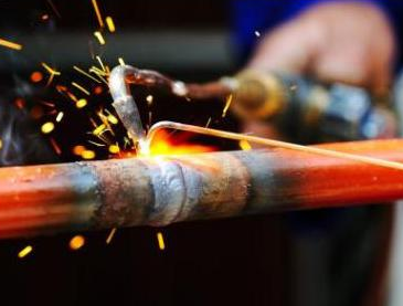
By definition, brazing is a metal-joining technique that uses a molten filler metal alloy having a melting temperature greater than about 425°C (800°F). In brazing, a filler metal is melted and drawn into a capillary formed by the assembly of two or more work pieces.

By definition, brazing is a metal-joining technique that uses a molten filler metal alloy having a melting temperature greater than about 425°C (800°F). In brazing, a filler metal is melted and drawn into a capillary formed by the assembly of two or more work pieces. The filler metal has a lower melting point than the adjoining metal. Brazing differs from welding in that it does not involve melting the work pieces and from soldering in using higher temperatures for a similar process, while also requiring much more closely fitted parts than when soldering. The filler metal flows between the closely fitting joint surfaces by means of capillary action.

Advantages and Disadvantages of Brazing

Advantages:

  • Strong, uniform, leakproof joints can be made rapidly, inexpensively, and even simultaneously.
  • Joints that are inaccessible and parts that may not be joinable at all by other methods often can be joined by brazing.
  • A major advantage of brazing is the ability to join the same or different metals with considerable strength.

Disadvantages:

  • One of the main disadvantages is the lack of joint strength as compared to a welded joint due to the softer filler metals used.
  • The strength of the brazed joint is likely to be less than that of the base metal(s) but greater than the filler metal.
  • Another disadvantage is that brazed joints can be damaged under high service temperatures.

Brazing Filler Material

A variety of alloys are used as filler metals for brazing depending on the intended use or application method. For manual brazing, wire and rod forms are generally used as they are the easiest to apply while heating. Some of the more common types of filler metals used are:

  • Aluminum-silicon
  • Copper
  • Copper-silver
  • Copper-zinc (brass)
  • Copper-tin (bronze)
  • Gold-silver
  • Nickel alloy
References:
Materials Science:

U.S. Department of Energy, Material Science. DOE Fundamentals Handbook, Volume 1 and 2. January 1993.
U.S. Department of Energy, Material Science. DOE Fundamentals Handbook, Volume 2 and 2. January 1993.
William D. Callister, David G. Rethwisch. Materials Science and Engineering: An Introduction 9th Edition, Wiley; 9 edition (December 4, 2013), ISBN-13: 978-1118324578.
Eberhart, Mark (2003). Why Things Break: Understanding the World by the Way It Comes Apart. Harmony. ISBN 978-1-4000-4760-4.
Gaskell, David R. (1995). Introduction to the thermodynamics of Materials (4th ed.). Taylor and Francis Publishing. ISBN 978-1-56032-992-3.
González-Viñas, W. & Mancini, H.L. (2004). An Introduction to Materials Science. Princeton University Press. ISBN 978-0-691-07097-1.
Ashby, Michael; Hugh Shercliff; David Cebon (2007). Materials: engineering, science, processing and design (1st ed.). Butterworth-Heinemann. ISBN 978-0-7506-8391-3.
J. R. Lamarsh, A. J. Baratta, Introduction to Nuclear Engineering, 3d ed., Prentice-Hall, 2001, ISBN: 0-201-82498-1.

See above:
Metal Joining

We hope, this article, Brazing, helps you. If so, give us a like in the sidebar. Main purpose of this website is to help the public to learn some interesting and important information about materials and their properties.

What are Oxydizing – Neutral – Reducing Flames – Definition

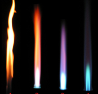
The temperature at which it burns is a function of the amount of oxygen present in the gas mixture. The figure demonstrates three types of flames that can be produced with oxyacetylene mixtures. Oxydizing – Neutral – Reducing Flames
Oxydizing – Neutral – Reducing Flames
Bunsen burner: leftmost: reducing flame, rightmost: oxidizing flame Source: wikipedia.org License: CC-BY SA 3.0

The temperature at which it burns is a function of the amount of oxygen present in the gas mixture. The figure demonstrates three types of flames that can be produced with oxyacetylene mixtures. Welding is generally carried out using the neutral flame setting which has equal quantities of oxygen and acetylene.

  • Reducing flame. The reducing flame is the flame with low oxygen and an excess of acetylene. Flame has a secondary feather extending from the inner cone. This secondary feather is caused by excess acetylene in the flame mixture, which alters the chemical composition of the weld pool by reducing iron oxide (reducing effect) and adding carbon (carburizing effect). It has a yellow or yellowish color due to carbon or hydrocarbons.
  • Neutral flame. The neutral flame is the flame in which the amount of oxygen is precisely enough for burning, and neither oxidation nor reduction occurs. The flame is considered neutral because it neither significantly adds to nor subtracts any elements from the weld pool. A flame with a good balance of oxygen is clear blue.
  • Oxydizing flame. The oxidizing flame is the flame produced with an excessive amount of oxygen. When the amount of oxygen increases, the flame shortens, its color darkens, and it hisses and roars. Since, as its name suggests, it oxidizes the metal’s surface, this flame has a harmful effect on the properties of ferrous alloys. With some exceptions (e.g., platinum soldering in jewelry), the oxidizing flame is usually undesirable for welding and soldering.
References:
Materials Science:

U.S. Department of Energy, Material Science. DOE Fundamentals Handbook, Volume 1 and 2. January 1993.
U.S. Department of Energy, Material Science. DOE Fundamentals Handbook, Volume 2 and 2. January 1993.
William D. Callister, David G. Rethwisch. Materials Science and Engineering: An Introduction 9th Edition, Wiley; 9 edition (December 4, 2013), ISBN-13: 978-1118324578.
Eberhart, Mark (2003). Why Things Break: Understanding the World by the Way It Comes Apart. Harmony. ISBN 978-1-4000-4760-4.
Gaskell, David R. (1995). Introduction to the thermodynamics of Materials (4th ed.). Taylor and Francis Publishing. ISBN 978-1-56032-992-3.
González-Viñas, W. & Mancini, H.L. (2004). An Introduction to Materials Science. Princeton University Press. ISBN 978-0-691-07097-1.
Ashby, Michael; Hugh Shercliff; David Cebon (2007). Materials: engineering, science, processing and design (1st ed.). Butterworth-Heinemann. ISBN 978-0-7506-8391-3.
J. R. Lamarsh, A. J. Baratta, Introduction to Nuclear Engineering, 3d ed., Prentice-Hall, 2001, ISBN: 0-201-82498-1.

See above:
Welding

We hope, this article, Oxydizing – Neutral – Reducing Flames, helps you. If so, give us a like in the sidebar. Main purpose of this website is to help the public to learn some interesting and important information about materials and their properties.

What is Friction Welding – Definition

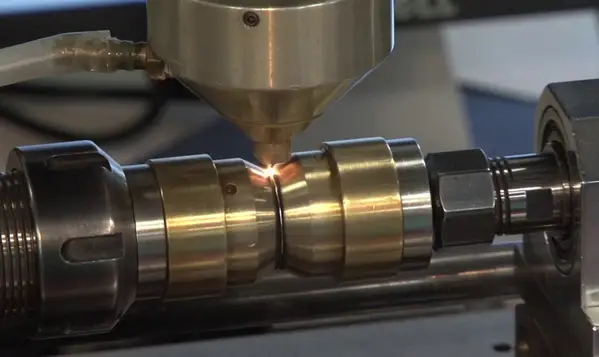
Friction welding is a form of solid state welding where the heat is obtained from the mechanically induced sliding motion between the parts to be welded. In solid state welding the joint is produced by the application o f pressure without significant melting any of the work parts.

Friction welding is a form of solid state welding where the heat is obtained from the mechanically induced sliding motion between the parts to be welded. In solid state welding the joint is produced by the application o f pressure without significant melting any of the work parts. Because no melting occurs, friction welding is not a fusion welding process in the traditional sense. The weld parts are held together under pressure. Generally, the frictional heat is generated by rotating one part against the other. When certain temperature is reached, the rotational motion is seized and the pressure applied welds the parts together. The bonding process is based either on deformation or on diffusion and limited deformation, so that atomic movement (diffusion) creates new bonds between atoms of two surfaces. The time required to generate friction welds is measured in seconds.

Friction Welding – Advantages and Disadvantages

The combination of fast joining times (on the order of a few seconds) and direct heat input at the weld interface yields relatively small heat-affected zones. If automatic loading and unloading devices are installed, the machines are completely automatic. Shielding gas, flux, and filler metal need not be used. This process successfully joins a wide range of similar materials as well as a number of dissimilar metals, including aluminum to steel. This is particularly useful in aerospace, where it is used to join lightweight aluminum stock to high-strength steels.

On the other hand, the work piece has its dimensional limitations. FRW is restricted mostly for round bars with similar cross-section, pieces of other forms are still possible to wield but it is much harder. Friction welding usually uses specific rotary machine, which needs higher capital costs.

References:
Materials Science:

U.S. Department of Energy, Material Science. DOE Fundamentals Handbook, Volume 1 and 2. January 1993.
U.S. Department of Energy, Material Science. DOE Fundamentals Handbook, Volume 2 and 2. January 1993.
William D. Callister, David G. Rethwisch. Materials Science and Engineering: An Introduction 9th Edition, Wiley; 9 edition (December 4, 2013), ISBN-13: 978-1118324578.
Eberhart, Mark (2003). Why Things Break: Understanding the World by the Way It Comes Apart. Harmony. ISBN 978-1-4000-4760-4.
Gaskell, David R. (1995). Introduction to the thermodynamics of Materials (4th ed.). Taylor and Francis Publishing. ISBN 978-1-56032-992-3.
González-Viñas, W. & Mancini, H.L. (2004). An Introduction to Materials Science. Princeton University Press. ISBN 978-0-691-07097-1.
Ashby, Michael; Hugh Shercliff; David Cebon (2007). Materials: engineering, science, processing and design (1st ed.). Butterworth-Heinemann. ISBN 978-0-7506-8391-3.
J. R. Lamarsh, A. J. Baratta, Introduction to Nuclear Engineering, 3d ed., Prentice-Hall, 2001, ISBN: 0-201-82498-1.

See above:
Welding

We hope, this article, Friction Welding, helps you. If so, give us a like in the sidebar. Main purpose of this website is to help the public to learn some interesting and important information about materials and their properties.

What is Oxyfuel Gas Welding – Oxyacetylene Welding – Definition

Gas welding utilizes the heat produced by a gas flame to melt the filler metal, if used, and the base metal, thereby creating a weld. Gas welding is one of the oldest and most versatile welding processes, but in recent years it has become less popular in industrial applications.

Oxyfuel Gas Welding

Oxyfuel Gas WeldingGas welding utilizes the heat produced by a gas flame to melt the filler metal, if used, and the base metal, thereby creating a weld. Gas welding is one of the oldest and most versatile welding processes, but in recent years it has become less popular in industrial applications. It is still widely used for welding pipes and tubes, as well as repair work. A similar process, generally called oxyfuel cutting, is used to cut metals.
The most common gas welding process is oxyacetylene welding. The equipment is relatively inexpensive and simple, generally employing the combustion of acetylene in oxygen to produce a welding flame temperature of about 3100 °C. Pure oxygen, instead of air, is used to increase the flame temperature to allow localized melting of the workpiece material. The temperature at which it burns is a function of the amount of oxygen present in the gas mixture.

Gases for Oxyfuel Welding

A common gases are:

  • Acetylene – Oxygen. Compared with other fuel gases, oxyacetylene can produce the hottest and most concentrated flame. The oxyacetylene flame also produces carbon dioxide, which serves as a shielding gas. Oxyacetylene flame burns at about 3,773 K (3,500 °C; 6,332 °F). As a fuel acetylene’s primary disadvantage, in comparison to other fuels, is high cost.
  • Stabilized methylacetylene-propadiene (MPS) has the storage and shipping characteristics of LPG and has a heat value a little lower than that of acetylene. MPS is recommended for cutting applications in particular, rather than welding applications.
  • Hydrogen – Oxygen. Hydrogen has a clean flame and is good for use on aluminium. It can be used at a higher pressure than acetylene and is therefore useful for underwater welding and cutting. It is a good type of flame to use when heating large amounts of material. Hydrogen is not used for welding steels and other ferrous materials, because it causes hydrogen embrittlement. Oxyhydrogen flame burns at 3,073 K (2,800 °C; 5,072 °F).

Oxydizing – Neutral – Reducing Flames

The temperature at which it burns is a function of the amount of oxygen present in the gas mixture. The figure demonstrates three types of flames that can be produced with oxyacetylene mixtures. Welding is generally carried out using the neutral flame setting which has equal quantities of oxygen and acetylene.

  • Reducing flame. The reducing flame is the flame with low oxygen and an excess of acetylene. Flame has a secondary feather extending from the inner cone. This secondary feather is caused by excess acetylene in the flame mixture, which alters the chemical composition of the weld pool by reducing iron oxide (reducing effect) and adding carbon (carburizing effect). It has a yellow or yellowish color due to carbon or hydrocarbons.
  • Neutral flame. The neutral flame is the flame in which the amount of oxygen is precisely enough for burning, and neither oxidation nor reduction occurs. The flame is considered neutral because it neither significantly adds to nor subtracts any elements from the weld pool. A flame with a good balance of oxygen is clear blue.
  • Oxydizing flame. The oxidizing flame is the flame produced with an excessive amount of oxygen. When the amount of oxygen increases, the flame shortens, its color darkens, and it hisses and roars. Since, as its name suggests, it oxidizes the metal’s surface, this flame has a harmful effect on the properties of ferrous alloys. With some exceptions (e.g., platinum soldering in jewelry), the oxidizing flame is usually undesirable for welding and soldering.
References:
Materials Science:

U.S. Department of Energy, Material Science. DOE Fundamentals Handbook, Volume 1 and 2. January 1993.
U.S. Department of Energy, Material Science. DOE Fundamentals Handbook, Volume 2 and 2. January 1993.
William D. Callister, David G. Rethwisch. Materials Science and Engineering: An Introduction 9th Edition, Wiley; 9 edition (December 4, 2013), ISBN-13: 978-1118324578.
Eberhart, Mark (2003). Why Things Break: Understanding the World by the Way It Comes Apart. Harmony. ISBN 978-1-4000-4760-4.
Gaskell, David R. (1995). Introduction to the thermodynamics of Materials (4th ed.). Taylor and Francis Publishing. ISBN 978-1-56032-992-3.
González-Viñas, W. & Mancini, H.L. (2004). An Introduction to Materials Science. Princeton University Press. ISBN 978-0-691-07097-1.
Ashby, Michael; Hugh Shercliff; David Cebon (2007). Materials: engineering, science, processing and design (1st ed.). Butterworth-Heinemann. ISBN 978-0-7506-8391-3.
J. R. Lamarsh, A. J. Baratta, Introduction to Nuclear Engineering, 3d ed., Prentice-Hall, 2001, ISBN: 0-201-82498-1.

See above:
Welding

We hope, this article, Oxyfuel Gas Welding – Oxyacetylene Welding, helps you. If so, give us a like in the sidebar. Main purpose of this website is to help the public to learn some interesting and important information about materials and their properties.

What are Gases for Oxyfuel Welding – Acetylene – MPS – Hydrogen – Definition

Gases for Oxyfuel Welding. A common gases are: Acetylene – Oxygen, Stabilized methylacetylene-propadiene (MPS), Hydrogen – Oxygen.

The most common gas welding process is oxyacetylene welding. The equipment is relatively inexpensive and simple, generally employing the combustion of acetylene in oxygen to produce a welding flame temperature of about 3100 °C. Pure oxygen, instead of air, is used to increase the flame temperature to allow localized melting of the workpiece material. The temperature at which it burns is a function of the amount of oxygen present in the gas mixture.

Gases for Oxyfuel Welding

A common gases are:

  • Acetylene – Oxygen. Compared with other fuel gases, oxyacetylene can produce the hottest and most concentrated flame. The oxyacetylene flame also produces carbon dioxide, which serves as a shielding gas. Oxyacetylene flame burns at about 3,773 K (3,500 °C; 6,332 °F). As a fuel acetylene’s primary disadvantage, in comparison to other fuels, is high cost.
  • Stabilized methylacetylene-propadiene (MPS) has the storage and shipping characteristics of LPG and has a heat value a little lower than that of acetylene. MPS is recommended for cutting applications in particular, rather than welding applications.
  • Hydrogen – Oxygen. Hydrogen has a clean flame and is good for use on aluminium. It can be used at a higher pressure than acetylene and is therefore useful for underwater welding and cutting. It is a good type of flame to use when heating large amounts of material. Hydrogen is not used for welding steels and other ferrous materials, because it causes hydrogen embrittlement. Oxyhydrogen flame burns at 3,073 K (2,800 °C; 5,072 °F).
References:
Materials Science:

U.S. Department of Energy, Material Science. DOE Fundamentals Handbook, Volume 1 and 2. January 1993.
U.S. Department of Energy, Material Science. DOE Fundamentals Handbook, Volume 2 and 2. January 1993.
William D. Callister, David G. Rethwisch. Materials Science and Engineering: An Introduction 9th Edition, Wiley; 9 edition (December 4, 2013), ISBN-13: 978-1118324578.
Eberhart, Mark (2003). Why Things Break: Understanding the World by the Way It Comes Apart. Harmony. ISBN 978-1-4000-4760-4.
Gaskell, David R. (1995). Introduction to the thermodynamics of Materials (4th ed.). Taylor and Francis Publishing. ISBN 978-1-56032-992-3.
González-Viñas, W. & Mancini, H.L. (2004). An Introduction to Materials Science. Princeton University Press. ISBN 978-0-691-07097-1.
Ashby, Michael; Hugh Shercliff; David Cebon (2007). Materials: engineering, science, processing and design (1st ed.). Butterworth-Heinemann. ISBN 978-0-7506-8391-3.
J. R. Lamarsh, A. J. Baratta, Introduction to Nuclear Engineering, 3d ed., Prentice-Hall, 2001, ISBN: 0-201-82498-1.

See above:
Welding

We hope, this article, Gases for Oxyfuel Welding – Acetylene – MPS – Hydrogen, helps you. If so, give us a like in the sidebar. Main purpose of this website is to help the public to learn some interesting and important information about materials and their properties.

What is Resistance Seam Welding – RSEW – Definition

Resistance seam welding is a process similar to that of spot welding process, but instead of pointed electrodes, wheel-shaped electrodes roll along and often feed the workpiece, making it possible to make long continuous welds.

Resistance welding (ERW) is a welding process which involves the generation of heat from the flow of electrical current through the parts being joined. Small pools of molten metal are formed at the weld area as high current (1000–100,000 A) is passed through the metal. Electric resistance welding is widely used, for example, in manufacture of steel pipe and in assembly of bodies for automobiles. The vehicle manufacturing industry, among others, employs the resistance processes extensively in applications in which the product design specifies gauge thicknesses that are lapped. Fully automatic and robotic systems are used for many of these applications.

Commonly implemented resistance welding processes are:

  • resistance spot welding (RSW),
  • resistance seam welding (RSEW),
  • resistance projection welding (RPW)
  • resistance stud welding.

The main process variables associated with these resistance welding processes are welding current, welding time, electrode force or pressure, electrode material, and tip configuration. Resistance welding (RW) was invented in 1886 by Professor Elihu Thomson, and it is one of the simplest and most commonplace fusion welding processes.

Resistance Seam Welding – RSEW

Resistance seam welding is a process similar to that of spot welding process, but instead of pointed electrodes, wheel-shaped electrodes roll along and often feed the workpiece, making it possible to make long continuous welds. This produces a weld at the faying surfaces of two similar metals. The electrodes are often disc shaped and rotate as the material passes between them. The seam may be a butt joint or an overlap joint and is usually an automated process. The joint is normally gastight or liquidtight. A series of welds is made without retracting the electrode wheels or releasing the electrode force between spots, but the wheels may advance either intermittently or continuously.

Like spot welding, seam welding relies on two electrodes, usually made from copper, to apply pressure and current. Seam welding produces an extremely durable weld because the joint is forged due to the heat and pressure applied. A common use of seam welding is during the manufacture of round or rectangular steel tubing.

References:
Materials Science:

U.S. Department of Energy, Material Science. DOE Fundamentals Handbook, Volume 1 and 2. January 1993.
U.S. Department of Energy, Material Science. DOE Fundamentals Handbook, Volume 2 and 2. January 1993.
William D. Callister, David G. Rethwisch. Materials Science and Engineering: An Introduction 9th Edition, Wiley; 9 edition (December 4, 2013), ISBN-13: 978-1118324578.
Eberhart, Mark (2003). Why Things Break: Understanding the World by the Way It Comes Apart. Harmony. ISBN 978-1-4000-4760-4.
Gaskell, David R. (1995). Introduction to the thermodynamics of Materials (4th ed.). Taylor and Francis Publishing. ISBN 978-1-56032-992-3.
González-Viñas, W. & Mancini, H.L. (2004). An Introduction to Materials Science. Princeton University Press. ISBN 978-0-691-07097-1.
Ashby, Michael; Hugh Shercliff; David Cebon (2007). Materials: engineering, science, processing and design (1st ed.). Butterworth-Heinemann. ISBN 978-0-7506-8391-3.
J. R. Lamarsh, A. J. Baratta, Introduction to Nuclear Engineering, 3d ed., Prentice-Hall, 2001, ISBN: 0-201-82498-1.

See above:
Welding

We hope, this article, Resistance Seam Welding – RSEW, helps you. If so, give us a like in the sidebar. Main purpose of this website is to help the public to learn some interesting and important information about materials and their properties.

What is Laser Beam Welding – Definition

Laser beam welding is one of high-power-density welding processes (on the order of 1 MW/cm2), which utilize a very high rate of heat input. These processes usually require automation and have excellent potential for high-speed production.

laser beam weldingLaser beam welding is one of high-power-density welding processes (on the order of 1 MW/cm2), which utilize a very high rate of heat input. These processes usually require automation and have excellent potential for high-speed production. Laser beam welding uses effects the fusion welding of materials with the heat supplied by a laser beam that impinges on the joint. A laser is a device that emits light through a process of optical amplification based on the stimulated emission of electromagnetic radiation. For weldinf purposes, laser beam is coherent, monochromatic light in the infrared or ultraviolet frequency portion of the electromagnetic radiation spectrum. Therefore, the beam is invisible. Commercial carbon dioxide (CO2) lasers can emit many hundreds of watts in a single spatial mode which can be concentrated into a tiny spot. This emission is in the thermal infrared at 10.6 µm; such lasers are regularly used in industry for cutting and welding. The minimally divergent raw beam is focused into a small spotto obtain greatest power density.
Laser Beam Welding – Advantages and Disadvantages

The main benefits include good flexibility, improved productivity with substantial saving on maintenance and energy cost while producing a strong weld. Metal sheets having thickness in the range 0.2 to 6mm can easily be laser welded. Majority of the automotive industries employ cross flow CO2 laser system in the power range of 3 to 5 kW. A special caution must be taken to personal safety. A safety enclosure is mandatory for protection against scattered radiation. The appropriate protective eyewear and clothing for the given type of laser must be used. Laser equipment is highly sophisticated and expensive, requiring knowledgeable personnel to install it and set parameters. Therefore this process  requires automation and has excellent potential for high-speed production.

References:
Materials Science:

U.S. Department of Energy, Material Science. DOE Fundamentals Handbook, Volume 1 and 2. January 1993.
U.S. Department of Energy, Material Science. DOE Fundamentals Handbook, Volume 2 and 2. January 1993.
William D. Callister, David G. Rethwisch. Materials Science and Engineering: An Introduction 9th Edition, Wiley; 9 edition (December 4, 2013), ISBN-13: 978-1118324578.
Eberhart, Mark (2003). Why Things Break: Understanding the World by the Way It Comes Apart. Harmony. ISBN 978-1-4000-4760-4.
Gaskell, David R. (1995). Introduction to the thermodynamics of Materials (4th ed.). Taylor and Francis Publishing. ISBN 978-1-56032-992-3.
González-Viñas, W. & Mancini, H.L. (2004). An Introduction to Materials Science. Princeton University Press. ISBN 978-0-691-07097-1.
Ashby, Michael; Hugh Shercliff; David Cebon (2007). Materials: engineering, science, processing and design (1st ed.). Butterworth-Heinemann. ISBN 978-0-7506-8391-3.
J. R. Lamarsh, A. J. Baratta, Introduction to Nuclear Engineering, 3d ed., Prentice-Hall, 2001, ISBN: 0-201-82498-1.

See above:
Welding

We hope, this article, Laser Beam Welding, helps you. If so, give us a like in the sidebar. Main purpose of this website is to help the public to learn some interesting and important information about materials and their properties.

What is Resistance Welding – Definition

Resistance welding (ERW) is a welding process which involves the generation of heat from the flow of electrical current through the parts being joined.

Resistance spot weldingResistance welding (ERW) is a welding process which involves the generation of heat from the flow of electrical current through the parts being joined. Small pools of molten metal are formed at the weld area as high current (1000–100,000 A) is passed through the metal. Electric resistance welding is widely used, for example, in manufacture of steel pipe and in assembly of bodies for automobiles. The vehicle manufacturing industry, among others, employs the resistance processes extensively in applications in which the product design specifies gauge thicknesses that are lapped. Fully automatic and robotic systems are used for many of these applications.

Commonly implemented resistance welding processes are:

  • resistance spot welding (RSW),
  • resistance seam welding (RSEW),
  • resistance projection welding (RPW)
  • resistance stud welding.

The main process variables associated with these resistance welding processes are welding current, welding time, electrode force or pressure, electrode material, and tip configuration. Resistance welding (RW) was invented in 1886 by Professor Elihu Thomson, and it is one of the simplest and most commonplace fusion welding processes.

Resistance Spot Welding – RSW

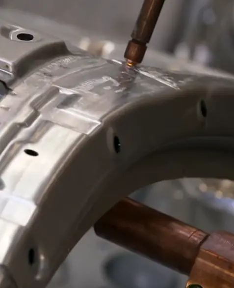
Resistance spot welding, or spot welding is a welding process used to join two or more overlapping metal sheets, studs, projections or another closely fitted surfaces in one or more spots. In this  method the joint is produced by the heat generated due to the resistance of work pieces to the flow of current and application of pressure. The weld is limited to the spots on overlapped work pieces and hence not continuous. The pointed copper electrodes conduct the welding current to the work spot and also serve to apply pressure to form the strong joint. These contacting surfaces are heated by a short-timed pulse of low-voltage, high-amperage current to form a fused nugget of weld metal. Small pools of molten metal are formed at the weld area as high current (1000–100,000 A) is passed through the metal. When the flow of current is stopped, the electrode pressure is maintained while the weld metal cools rapidly and solidifies. The electrodes are made of either precipitationed strengthened copper-chromium and/or zirconium alloy and have to be exchanged after a certain amount of welds.

The advantages of the method include efficient energy use, limited workpiece deformation, high production rates, easy automation, and no required filler materials. The principal disadvantage is the need to have accessibility to both sides of the workpiece as opposed to being able to make welds from one side only. The most commonly used welding methods for automotive applications include resistance spot welding (RSW). The vehicle manufacturing industry, among others, employs the resistance processes extensively in applications in which the product design specifies gauge thicknesses that are lapped. Fully automatic and robotic systems are used for many of these applications. The conventional steel body of a car, on an average, contains 4500 spot weld joints.

Resistance Seam Welding – RSEW

Resistance seam welding is a process similar to that of spot welding process, but instead of pointed electrodes, wheel-shaped electrodes roll along and often feed the workpiece, making it possible to make long continuous welds. This produces a weld at the faying surfaces of two similar metals. The electrodes are often disc shaped and rotate as the material passes between them. The seam may be a butt joint or an overlap joint and is usually an automated process. The joint is normally gastight or liquidtight. A series of welds is made without retracting the electrode wheels or releasing the electrode force between spots, but the wheels may advance either intermittently or continuously.

Like spot welding, seam welding relies on two electrodes, usually made from copper, to apply pressure and current. Seam welding produces an extremely durable weld because the joint is forged due to the heat and pressure applied. A common use of seam welding is during the manufacture of round or rectangular steel tubing.

References:
Materials Science:

U.S. Department of Energy, Material Science. DOE Fundamentals Handbook, Volume 1 and 2. January 1993.
U.S. Department of Energy, Material Science. DOE Fundamentals Handbook, Volume 2 and 2. January 1993.
William D. Callister, David G. Rethwisch. Materials Science and Engineering: An Introduction 9th Edition, Wiley; 9 edition (December 4, 2013), ISBN-13: 978-1118324578.
Eberhart, Mark (2003). Why Things Break: Understanding the World by the Way It Comes Apart. Harmony. ISBN 978-1-4000-4760-4.
Gaskell, David R. (1995). Introduction to the thermodynamics of Materials (4th ed.). Taylor and Francis Publishing. ISBN 978-1-56032-992-3.
González-Viñas, W. & Mancini, H.L. (2004). An Introduction to Materials Science. Princeton University Press. ISBN 978-0-691-07097-1.
Ashby, Michael; Hugh Shercliff; David Cebon (2007). Materials: engineering, science, processing and design (1st ed.). Butterworth-Heinemann. ISBN 978-0-7506-8391-3.
J. R. Lamarsh, A. J. Baratta, Introduction to Nuclear Engineering, 3d ed., Prentice-Hall, 2001, ISBN: 0-201-82498-1.

See above:
Welding

We hope, this article, Resistance Welding, helps you. If so, give us a like in the sidebar. Main purpose of this website is to help the public to learn some interesting and important information about materials and their properties.