A planar defect is a discontinuity of the perfect crystal structure across a plane. Interfacial defects are boundaries that have two dimensions and normally separate regions of the materials that have different crystal structures and/or crystallographic orientations. Interfacial defects exist at an angle between any two faces of a crystal or crystal form. These imperfections are found at free surfaces, domain boundaries, grain boundaries, or interphase boundaries.
Grain Boundaries
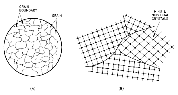
A grain boundary is a general planar defect that separates regions of different crystalline orientation (i.e. grains) within a polycrystalline solid. Up to this point, the discussion has focused on defects of single crystals. However, solids generally consist of a number of crystallites or grains of varying size and orientation. These have random crystallographic orientations. When a metal starts with crystallization, the phase change begins with small crystals that grow until they fuse, forming a polycrystalline structure. In the final block of solid material, each of the small crystals (called “grains“) is a true crystal with a periodic arrangement of atoms, but the whole polycrystal does not have a periodic arrangement of atoms, because the periodic pattern is broken at the grain boundaries. Grains and grain boundaries help determine the properties of a material. Grains can range in size from nanometers to millimeters across and their orientations are usually rotated with respect to neighboring grains. Where one grain stops and another begins is known as a grain boundary. Grain boundaries limit the lengths and motions of dislocations. Therefore, having smaller grains (more grain boundary surface area) strengthens a material. The size of the grains can be controlled by the cooling rate when the material cast or heat treated. Generally, rapid cooling produces smaller grains whereas slow cooling result in larger grains.
- Grains, also known as crystallites, are small or even microscopic crystals which form, for example, during the cooling of many materials (crystallization). A very important feature of a metal is the average size of the grain. The size of the grain determines the properties of the metal. For example, smaller grain size increases tensile strength and tends to increase ductility. A larger grain size is preferred for improved high-temperature creep properties. Creep is the permanent deformation that increases with time under constant load or stress. Creep becomes progressively easier with increasing temperature.
- Grain Boundaries. The grain boundary refers to the outside area of a grain that separates it from the other grains. The grain boundaries separate variously-oriented crystal regions (polycrystalline) in which the crystal structures are identical. Grain boundaries are 2D defects in the crystal structure, and tend to decrease the electrical and thermal conductivity of the material. Most grain boundaries are preferred sites for the onset of corrosion and for the precipitation of new phases from the solid. They are also important to many of the mechanisms of creep. On the other hand, grain boundaries disrupt the motion of dislocations through a material. Dislocation propagation is impeded because of the stress field of the grain boundary defect region and the lack of slip planes and slip directions and overall alignment across the boundaries. Therefore reducing crystallite size is a common way to improve mechanical strength, because the smaller grains create more obstacles per unit area of slip plane.
Twinning – Twin Boundaries
Twinning is a phenomenon somewhere between a crystallographic defect and a grain boundary. Like a grain boundary, a twin boundary has different crystal orientations on its two sides. But unlike a grain boundary, the orientations are not random, but related in a specific, mirror-image way. A twin boundary happens when the crystals on either side of a plane are mirror images of each other.
The boundary between the twinned crystals will be a single plane of atoms. There is no region of disorder and the boundary atoms can be viewed as belonging to the crystal structures of both twins.
There are three modes of formation of twinned crystals. Twins are either grown-in during crystallisation, or the result of mechanical or thermal work. Grown twins are the result of an interruption or change in the lattice during formation or growth due to a possible deformation from a larger substituting ion. Annealing or transformation twins are the result of a change in crystal system during cooling as one form becomes unstable and the crystal structure must re-organize or transform into another more stable form. Deformation or gliding twins are the result of stress on the crystal after the crystal has formed.
Bulk Defects – Volume Defects
Three-dimensional macroscopic defects are called bulk defects. They generally occur on a much larger scale than the microscopic defects. These macroscopic defects generally are introduced into a material during refinement from its raw state or during fabrication processes. These include cracks, pores, foreign inclusions, and other phases. The working and forging of metals can cause cracks that act as stress concentrators and weaken the material. Any welding or joining defects may also be classified as bulk defects.
- Three-dimensional macroscopic or bulk defects, such as pores, cracks, or inclusions.
- Voids — small regions where there are no atoms, and which can be thought of as clusters of vacancies.
- Impurities can cluster together to form small regions of a different phase. These are often called precipitates.
We hope, this article, Planar Defects – Interfacial Defects, helps you. If so, give us a like in the sidebar. Main purpose of this website is to help the public to learn some interesting and important information about materials and their properties.