Facebook Instagram Youtube Twitter

Thermal Properties of Materials – Definition

Thermal properties of materials refer to the response of materials to changes in their temperature and to the application of heat. As a solid absorbs energy in the form of heat, its temperature rises and its dimensions increase.

Thermal properties of materials refer to the response of materials to changes in their thermodynamics/thermodynamic-properties/what-is-temperature-physics/”>temperature and to the application of heat. As a solid absorbs thermodynamics/what-is-energy-physics/”>energy in the form of heat, its temperature rises and its dimensions increase. But different materials react to the application of heat differently.

Heat capacity, thermal expansion, and thermal conductivity are properties that are often critical in the practical use of solids.

Melting Point – Boiling Point of Materials

Note that, these points are associated with the standard atmospheric pressure.

Melting Point

See also: Melting Points – Periodic Table

In general, melting is a phase change of a substance from the solid to the liquid phase. The melting point of a substance is the temperature at which this phase change occurs. The melting point also defines a condition in which the solid and liquid can exist in equilibrium. Adding a heat will convert the solid into a liquid with no temperature change. At the melting point the two phases of a substance, liquid and vapor, have identical free energies and therefore are equally likely to exist. Below the melting point, the solid is the more stable state of the two, whereas above the liquid form is preferred. The melting point of a substance depends on pressure and is usually specified at standard pressure. When considered as the temperature of the reverse change from liquid to solid, it is referred to as the freezing point or crystallization point.

See also: Melting Point Depression

The first theory explaining mechanism of melting in the bulk was proposed by Lindemann, who used vibration of atoms in the crystal to explain the melting transition. Solids are similar to liquids in that both are condensed states, with particles that are far closer together than those of a gas. The atoms in a solid are tightly bound to each other, either in a regular geometric lattice (crystalline solids, which include metals and ordinary ice) or irregularly (an amorphous solid such as common window glass), and are typically low in energy. The motion of individual atoms, ions, or molecules in a solid is restricted to vibrational motion about a fixed point. As a solid is heated, its particles vibrate more rapidly as the solid absorbs kinetic energy. At some point the amplitude of vibration becomes so large that the atoms start to invade the space of their nearest neighbors and disturb them and the melting process initiates. The melting point is the temperature at which the disruptive vibrations of the particles of the solid overcome the attractive forces operating within the solid.

As with boiling points, the melting point of a solid is dependent on the strength of those attractive forces. For example, sodium chloride  (NaCl) is an ionic compound that consists of a multitude of strong ionic bonds. Sodium chloride melts at  801°C. On the other hand, ice (solid H2O) is a molecular compound whose molecules are held together by hydrogen bonds, which is effectively a strong example of an interaction between two permanent dipoles. Though hydrogen bonds are the strongest of the intermolecular forces, the strength of hydrogen bonds is much less than that of ionic bonds. The melting point of ice is 0 °C.

Covalent bonds often result in the formation of small collections of better-connected atoms called molecules, which in solids and liquids are bound to other molecules by forces that are often much weaker than the covalent bonds that hold the molecules internally together. Such weak intermolecular bonds give organic molecular substances, such as waxes and oils, their soft bulk character, and their low melting points (in liquids, molecules must cease most structured or oriented contact with each other).

Boiling Point

See also: Boiling Points – Periodic Table

In general, boiling is a phase change of a substance from the liquid to the gas phase. The boiling point of a substance is the temperature at which this phase change (boiling or vaporization) occurs. The temperature at which vaporization (boiling) starts to occur for a given pressure is also known as the saturation temperature and at this conditions a mixture of vapor and liquid can exist together. The liquid can be said to be saturated with thermal energy. Any addition of thermal energy results in a phase transition. At the boiling point the two phases of a substance, liquid and vapor, have identical free energies and therefore are equally likely to exist. Below the boiling point, the liquid is the more stable state of the two, whereas above the gaseous form is preferred. The pressure at which vaporization (boiling) starts to occur for a given temperature is called the saturation pressure. When considered as the temperature of the reverse change from vapor to liquid, it is referred to as the condensation point.

As can be seen, the boiling point of a liquid varies depending upon the surrounding environmental pressure. A liquid in a partial vacuum has a lower boiling point than when that liquid is at atmospheric pressure. A liquid at high pressure has a higher boiling point than when that liquid is at atmospheric pressure. For example, water boils at 100°C (212°F) at sea level, but at 93.4°C (200.1°F) at 1900 metres (6,233 ft) altitude. On the other hand, water boils at 350°C (662°F) at 16.5 MPa (typical pressure of PWRs).

In the periodic table of elements, the element with the lowest boiling point is helium. Both the boiling points of rhenium and tungsten exceed 5000 K at standard pressure. Since it is difficult to measure extreme temperatures precisely without bias, both have been cited in the literature as having the higher boiling point.

melting and boiling point

Thermal Conductivity of Materials

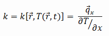
The heat transfer characteristics of a solid material are measured by a property called the thermal conductivity, k (or λ), measured in W/m.K. It is a measure of a substance’s ability to transfer heat through a material by conduction. Note that Fourier’s law applies for all matter, regardless of its state (solid, liquid, or gas), therefore, it is also defined for liquids and gases.

The thermal conductivity of most liquids and solids varies with temperature. For vapors, it also depends upon pressure. In general:
thermal conductivity - definition

Most materials are very nearly homogeneous, therefore we can usually write k = k (T). Similar definitions are associated with thermal conductivities in the y- and z-directions (ky, kz), but for an isotropic material the thermal conductivity is independent of the direction of transfer, kx = ky = kz = k.

Thermal Conductivity of Metals

Transport of thermal energy in solids may be generally due to two effects:
  • the migration of free electrons
  • lattice vibrational waves (phonons)

When electrons and phonons carry thermal energy leading to conduction heat transfer in a solid, the thermal conductivity may be expressed as:

k = ke + kph
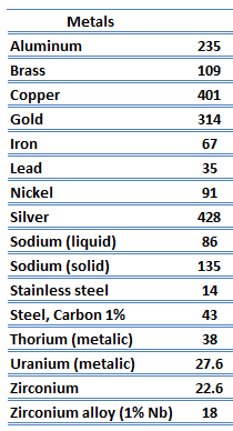
thermal conductivity - metalsMetals are solids and as such they possess crystalline structure where the ions (nuclei with their surrounding shells of core electrons) occupy translationally equivalent positions in the crystal lattice. Metals in general have high electrical conductivity, high thermal conductivity, and high density. Accordingly, transport of thermal energy may be due to two effects:

  • the migration of free electrons
  • lattice vibrational waves (phonons).

When electrons and phonons carry thermal energy leading to conduction heat transfer in a solid, the thermal conductivity may be expressed as:

k = ke + kph

The unique feature of metals as far as their structure is concerned is the presence of charge carriers, specifically electrons. The electrical and thermal conductivities of metals originate from the fact that their outer electrons are delocalized. Their contribution to the thermal conductivity is referred to as the electronic thermal conductivity, ke. In fact, in pure metals such as gold, silver, copper, and aluminum, the heat current associated with the flow of electrons by far exceeds a small contribution due to the flow of phonons. In contrast, for alloys, the contribution of kph to k is no longer negligible.

Thermal Conductivity of Nonmetals
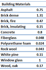
thermal conductivity - building materialsFor nonmetallic solids, k is determined primarily by kph, which increases as the frequency of interactions between the atoms and the lattice decreases. In fact, lattice thermal conduction is the dominant thermal conduction mechanism in nonmetals, if not the only one. In solids, atoms vibrate about their equilibrium positions (crystal lattice). The vibrations of atoms are not independent of each other, but are rather strongly coupled with neighboring atoms. The regularity of the lattice arrangement has an important effect on kph, with crystalline (well-ordered) materials like quartz having a higher thermal conductivity than amorphous materials like glass. At sufficiently high temperatures kph ∝ 1/T.

The quanta of the crystal vibrational field are referred to as ‘‘phonons.’’ A phonon is a collective excitation in a periodic, elastic arrangement of atoms or molecules in condensed matter, like solids and some liquids. Phonons play a major role in many of the physical properties of condensed matter, like thermal conductivity and electrical conductivity. In fact, for crystalline, nonmetallic solids such as diamond, kph can be quite large, exceeding values of k associated with good conductors, such as aluminum. In particular, diamond has the highest hardness and thermal conductivity (k = 1000 W/m.K) of any bulk material.

Thermal Conductivity of Liquids and Gases

In physics, a fluid is a substance that continually deforms (flows) under an applied shear stress. Fluids are a subset of the phases of matter and include liquids, gases, plasmas and, to some extent, plastic solids. Because the intermolecular spacing is much larger and the motion of the molecules is more random for the fluid state than for the solid state, thermal energy transport is less effective. The thermal conductivity of gases and liquids is therefore generally smaller than that of solids. In liquids, the thermal conduction is caused by atomic or molecular diffusion. In gases, the thermal conduction is caused by diffusion of molecules from higher energy level to the lower level.

Thermal Conductivity of Gases
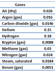
thermal conductivity - gasesThe effect of temperature, pressure, and chemical species on the thermal conductivity of a gas may be explained in terms of the kinetic theory of gases. Air and other gases are generally good insulators, in the absence of convection. Therefore, many insulating materials (e.g.polystyrene) function simply by having a large number of gas-filled pockets which prevent large-scale convection. Alternation of gas pocket and solid material causes that the heat must be transferred through many interfaces causing rapid decrease in heat transfer coefficient.

The thermal conductivity of gases is directly proportional to the density of the gas, the mean molecular speed, and especially to the mean free path of molecule. The mean free path also depends on the diameter of the molecule, with larger molecules more likely to experience collisions than small molecules, which is the average distance traveled by an energy carrier (a molecule) before experiencing a collision. Light gases, such as hydrogen and helium typically have high thermal conductivity. Dense gases such as xenon and dichlorodifluoromethane have low thermal conductivity.

In general, the thermal conductivity of gases increases with increasing temperature.

Thermal Conductivity of Liquids

As was written, in liquids, the thermal conduction is caused by atomic or molecular diffusion, but physical mechanisms for explaining the thermal conductivity of liquids are not well understood. Liquids tend to have better thermal conductivity than gases, and the ability to flow makes a liquid suitable for removing excess heat from mechanical components. The heat can be removed by channeling the liquid through a heat exchanger. The coolants used in nuclear reactors include water or liquid metals, such as sodium or lead.

The thermal conductivity of nonmetallic liquids generally decreases with increasing temperature.

Coefficient of Thermal Expansion of Materials

Thermal expansion is generally the tendency of matter to change its dimensions in response to a change in temperature. It is usually expressed as a fractional change in length or volume per unit temperature change. Thermal expansion is common for solids, liquids and for gases. Unlike gases or liquids, solid materials tend to keep their shape when undergoing thermal expansion. A linear expansion coefficient is usually employed in describing the expansion of a solid, while a volume expansion coefficient is more useful for a liquid or a gas.

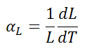
The linear thermal expansion coefficient is defined as:
linear thermal expansion coefficient - equation

where L is a particular length measurement and dL/dT is the rate of change of that linear dimension per unit change in temperature.

The volumetric thermal expansion coefficient is the most basic thermal expansion coefficient, and the most relevant for fluids. In general, substances expand or contract when their temperature changes, with expansion or contraction occurring in all directions.

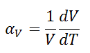
The volumetric thermal expansion coefficient is defined as:
volumetric thermal expansion coefficient - equation

where L is the volume of the material and dV/dT is the rate of change of that volume per unit change in temperature.

In a solid or liquid, there is a dynamic balance between the cohesive forces holding the atoms or molecules together and the conditions created by temperature. Therefore higher temperatures imply greater distance between atoms. Different materials have different bonding forces and therefore different expansion coefficients. If a crystalline solid is isometric (has the same structural configuration throughout), the expansion will be uniform in all dimensions of the crystal. For these materials, the area and volumetric thermal expansion coefficient are, respectively, approximately twice and three times larger than the linear thermal expansion coefficient (αV = 3αL). If it is not isometric, there may be different expansion coefficients for different crystallographic directions, and the crystal will change shape as the temperature changes.

Specific Heat of Materials

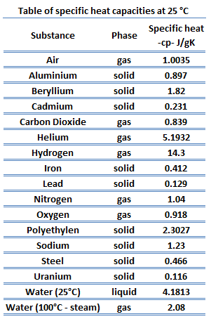
Specific heat, or specific heat capacity, is a property related to internal energy that is very important in thermodynamics. The intensive properties cv and cp are defined for pure, simple compressible substances as partial derivatives of the internal energy u(T, v) and enthalpy h(T, p), respectively:
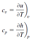
Table of specific heat capacitieswhere the subscripts v and p denote the variables held fixed during differentiation. The properties cv and cp are referred to as specific heats (or heat capacities) because under certain special conditions they relate the temperature change of a system to the amount of energy added by heat transfer. Their SI units are J/kg K or J/mol K.

Different substances are affected to different magnitudes by the addition of heat. When a given amount of heat is added to different substances, their temperatures increase by different amounts.

Heat capacity is an extensive property of matter, meaning it is proportional to the size of the system. Heat capacity C has the unit of energy per degree or energy per kelvin. When expressing the same phenomenon as an intensive property, the heat capacity is divided by the amount of substance, mass, or volume, thus the quantity is independent of the size or extent of the sample.
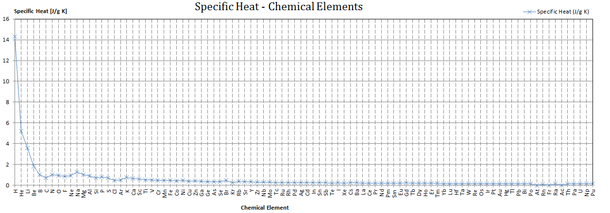
specific heat - heat capacity

Latent Heat of Vaporization of Materials

In general, when a material changes phase from solid to liquid, or from liquid to gas a certain amount of energy is involved in this change of phase. In case of liquid to gas phase change, this amount of energy is known as the enthalpy of vaporization, (symbol ∆Hvap; unit: J) also known as the (latent) heat of vaporization or heat of evaporation. As an example, see the figure, which descibes phase transitions of water.

Latent heat is the amount of heat added to or removed from a substance to produce a change in phase. This energy breaks down the intermolecular attractive forces, and also must provide the energy necessary to expand the gas (the pΔV work). When latent heat is added, no temperature change occurs. The enthalpy of vaporization is a function of the pressure at which that transformation takes place.

The temperature at which vaporization (boiling) starts to occur for a given pressure is also known as the saturation temperature and at this conditions a mixture of vapor and liquid can exist together. The liquid can be said to be saturated with thermal energy. Any addition of thermal energy results in a phase transition. At the boiling point the two phases of a substance, liquid and vapor, have identical free energies and therefore are equally likely to exist. Below the boiling point, the liquid is the more stable state of the two, whereas above the gaseous form is preferred.
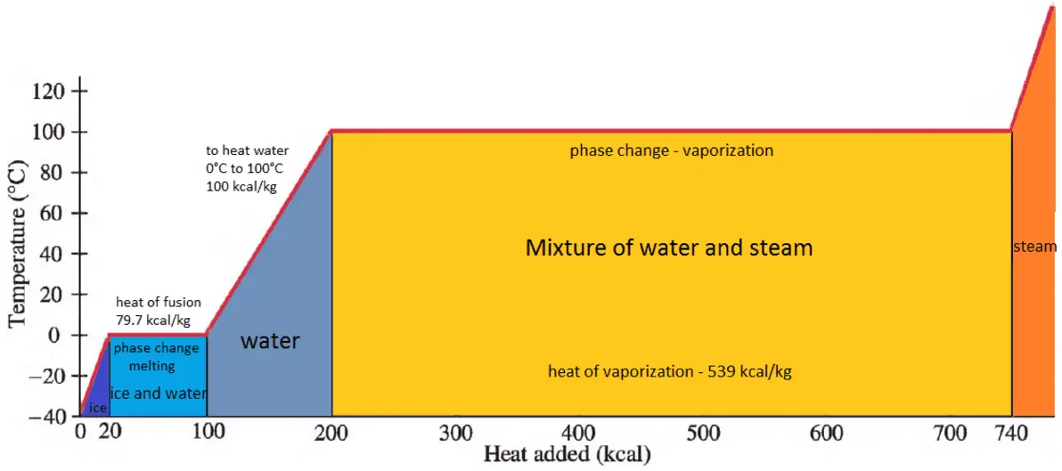
Phase changes - enthalpy of vaporization
Latent heat of vaporization – water at 0.1 MPa. Dominant part of heat absorbed.

Latent Heat of Fusion of Materials

In case of solid to liquid phase change, the change in enthalpy required to change its state is known as the enthalpy of fusion, (symbol ∆Hfus; unit: J) also known as the (latent) heat of fusion. Latent heat is the amount of heat added to or removed from a substance to produce a change in phase. This energy breaks down the intermolecular attractive forces, and also must provide the energy necessary to expand the system (the pΔV work).

The liquid phase has a higher internal energy than the solid phase. This means energy must be supplied to a solid in order to melt it and energy is released from a liquid when it freezes, because the molecules in the liquid experience weaker intermolecular forces and so have a higher potential energy (a kind of bond-dissociation energy for intermolecular forces).

The temperature at which the phase transition occurs is the melting point. The melting point also defines a condition in which the solid and liquid can exist in equilibrium. Adding a heat will convert the solid into a liquid with no temperature change. At the melting point the two phases of a substance, liquid and vapor, have identical free energies and therefore are equally likely to exist. Below the melting point, the solid is the more stable state of the two, whereas above the liquid form is preferred. The melting point of a substance depends on pressure and is usually specified at standard pressure. When considered as the temperature of the reverse change from liquid to solid, it is referred to as the freezing point or crystallization point.
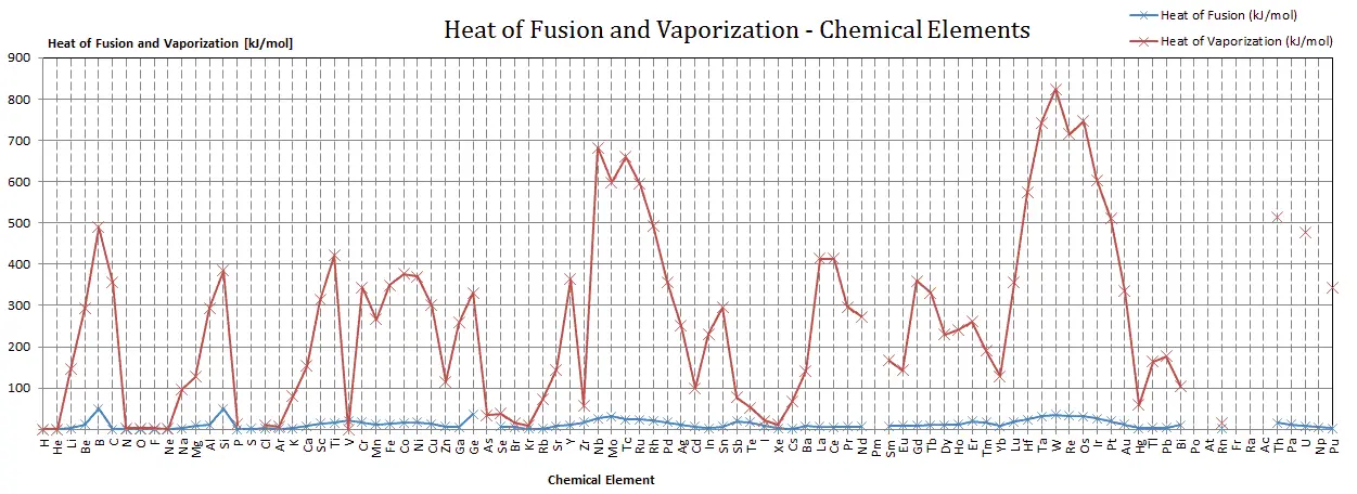
heat of fusion and vaporization

Emissivity of Materials

The emissivity, ε, of the surface of a material is its effectiveness in emitting energy as thermal radiation and varies between 0.0 and 1.0.
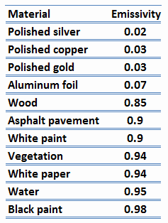
emissivity of various materialBy definition, a blackbody in thermal equilibrium has an emissivity of ε = 1.0. Real objects do not radiate as much heat as a perfect black body. They radiate less heat than a black body and therefore are called gray bodies. To take into account the fact that real objects are gray bodies, the Stefan-Boltzmann law must include emissivity. Quantitatively, emissivity is the ratio of the thermal radiation from a surface to the radiation from an ideal black surface at the same temperature as given by the Stefan–Boltzmann law. Emissivity is simply a factor by which we multiply the black body heat transfer to take into account that the black body is the ideal case.

The surface of a blackbody emits thermal radiation at the rate of approximately 448 watts per square metre at room temperature (25 °C, 298.15 K). Real objects with emissivities less than 1.0 (e.g. copper wire) emit radiation at correspondingly lower rates (e.g. 448 x 0.03 = 13.4 W/m2). Emissivity plays important role in heat transfer problems. For example, solar heat collectors incorporate selective surfaces that have very low emissivities. These collectors waste very little of the solar energy through emission of thermal radiation.

Another important radiation property of a surface is its absorptivity, α, which is the fraction of the radiation energy incident on a surface that is absorbed by the surface. Like emissivity, value of absorptivity is in the range 0 < α < 1.

In general, the absorptivity and the emissivity are interconnected by the Kirchhoff’s Law of thermal radiation, which states:

For an arbitrary body emitting and absorbing thermal radiation in thermodynamic equilibrium, the emissivity is equal to the absorptivity.

emissivity ε = absorptivity α

Note that visible radiation occupies a very narrow band of the spectrum from 0.4 to 0.76 nm, we cannot make any judgments about the blackness of a surface on the basis of visual observations. For example, consider white paper that reflects visible light and thus appear white. On the other hand it is essentially black for infrared radiation (absorptivity α = 0.94) since they strongly absorb long-wavelength radiation.

See also: Thermal Blanket

References:
Materials Science:
  1. U.S. Department of Energy, Material Science. DOE Fundamentals Handbook, Volume 1 and 2. January 1993.
  2. U.S. Department of Energy, Material Science. DOE Fundamentals Handbook, Volume 2 and 2. January 1993.
  3. William D. Callister, David G. Rethwisch. Materials Science and Engineering: An Introduction 9th Edition, Wiley; 9 edition (December 4, 2013), ISBN-13: 978-1118324578.
  4. Eberhart, Mark (2003). Why Things Break: Understanding the World by the Way It Comes Apart. Harmony. ISBN 978-1-4000-4760-4.
  5. Gaskell, David R. (1995). Introduction to the thermodynamics of Materials (4th ed.). Taylor and Francis Publishing. ISBN 978-1-56032-992-3.
  6. González-Viñas, W. & Mancini, H.L. (2004). An Introduction to Materials Science. Princeton University Press. ISBN 978-0-691-07097-1.
  7. Ashby, Michael; Hugh Shercliff; David Cebon (2007). Materials: engineering, science, processing and design (1st ed.). Butterworth-Heinemann. ISBN 978-0-7506-8391-3.
  8. J. R. Lamarsh, A. J. Baratta, Introduction to Nuclear Engineering, 3d ed., Prentice-Hall, 2001, ISBN: 0-201-82498-1.

See above:

Material Properties

We hope, this article, Thermal Properties of Materials, helps you. If so, give us a like in the sidebar. Main purpose of this website is to help the public to learn some interesting and important information about materials and their properties.
Stages of Creep – Primary – Secondary – Tertiary – Definition

Creep is time dependent and it goes through several stages: Primary – Secondary – Tertiary. In materials engineering, possibly the most important parameter from a creep test is the slope of the secondary portion of the creep curve (ΔP/Δt).

stages of creep - CreepCreep, known also as cold flow, is the permanent deformation that increases with time under constant load or stress. It results due to long time exposure to large external mechanical stress with in limit of yielding and is more severe in material that are subjected to heat for long time. The rate of deformation is a function of the material’s properties, exposure time, exposure thermodynamics/thermodynamic-properties/what-is-temperature-physics/”>temperature and the applied structural load. Creep is a very important phenomenon if we are using materials at high temperature. Creep is very important in power industry and it is of the highest importance in designing of jet engines. For many relatively short-life creep situations (e.g. turbine blades in military aircraft), time to rupture is the dominant design consideration. Of course, for its determination, creep tests must be conducted to the point of failure; these are termed creep rupture tests.

Stages of Creep

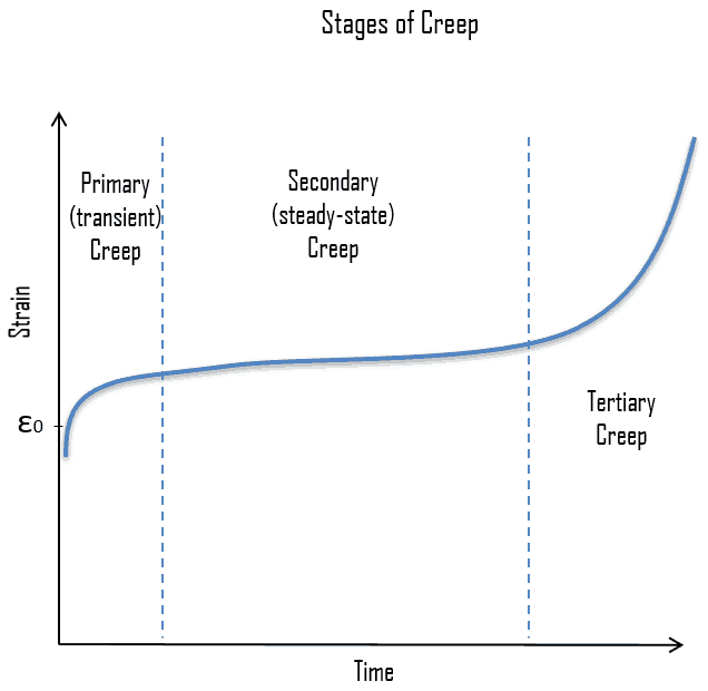
As can be seen from the figure, creep is time dependent and it goes through several stages:

  • Primary Creep. In the initial stage, or primary creep, or transient creep, the strain rate is relatively high, but decreases with increasing time and strain due the fact that the material is experiencing an increase in creep resistance or strain hardening. This is followed by secondary (or steady-state) creep in Stage II, when the creep rate is small and the strain increases very slowly with time.
  • Secondary Creep. For secondary creep, sometimes termed steady-state creep, the rate is constant—that is, the plot becomes nearly linear. The strain rate diminishes to a minimum and becomes near constant as the secondary stage begins. This is due to the balance between work hardening and annealing (thermal softening). This stage of creep is the most understood. The steady-state creep is often the stage of creep that is of the longest duration. No material strength is lost during these first two stages of creep. In materials engineering, possibly the most important parameter from a creep test is the slope of the secondary portion of the creep curve (ΔP/Δt). It is the engineering design parameter that is considered for long-life applications. This parameter is often called the minimum or steady-state creep rate.
  • Tertiary Creep. In tertiary creep, there is an acceleration of the rate and possibly ultimate failure. The strain rate exponentially increases with stress because of necking phenomena or internal cracks, cavities or voids decrease the effective area of the specimen. These all lead to a decrease in the effective cross-sectional area and an increase in strain rate. Strength is quickly lost in this stage while the material’s shape is permanently changed. The acceleration of creep deformation in the tertiary stage eventually leads to failure, which is frequently termed rupture and results from microstructural and/or metallurgical changes.

&nbsp;

References:
Materials Science:
  1. U.S. Department of Energy, Material Science. DOE Fundamentals Handbook, Volume 1 and 2. January 1993.
  2. U.S. Department of Energy, Material Science. DOE Fundamentals Handbook, Volume 2 and 2. January 1993.
  3. William D. Callister, David G. Rethwisch. Materials Science and Engineering: An Introduction 9th Edition, Wiley; 9 edition (December 4, 2013), ISBN-13: 978-1118324578.
  4. Eberhart, Mark (2003). Why Things Break: Understanding the World by the Way It Comes Apart. Harmony. ISBN 978-1-4000-4760-4.
  5. Gaskell, David R. (1995). Introduction to the thermodynamics of Materials (4th ed.). Taylor and Francis Publishing. ISBN 978-1-56032-992-3.
  6. González-Viñas, W. & Mancini, H.L. (2004). An Introduction to Materials Science. Princeton University Press. ISBN 978-0-691-07097-1.
  7. Ashby, Michael; Hugh Shercliff; David Cebon (2007). Materials: engineering, science, processing and design (1st ed.). Butterworth-Heinemann. ISBN 978-0-7506-8391-3.
  8. J. R. Lamarsh, A. J. Baratta, Introduction to Nuclear Engineering, 3d ed., Prentice-Hall, 2001, ISBN: 0-201-82498-1.

See above:

Creep

We hope, this article, Stages of Creep – Primary – Secondary – Tertiary, helps you. If so, give us a like in the sidebar. Main purpose of this website is to help the public to learn some interesting and important information about materials and their properties.
Creep Prevention – Creep Resistance – Definition

Creep prevention is based on the proper choice of material is also crucial. Creep resistance of materials can be influenced by many factors such as diffusivity, precipitate and grain size.

Creep, known also as cold flow, is the permanent deformation that increases with time under constant load or stress. It results due to long time exposure to large external mechanical stress with in limit of yielding and is more severe in material that are subjected to heat for long time. The rate of deformation is a function of the material’s properties, exposure time, exposure thermodynamics/thermodynamic-properties/what-is-temperature-physics/”>temperature and the applied structural load. Creep is a very important phenomenon if we are using materials at high temperature. Creep is very important in power industry and it is of the highest importance in designing of jet engines. For many relatively short-life creep situations (e.g. turbine blades in military aircraft), time to rupture is the dominant design consideration. Of course, for its determination, creep tests must be conducted to the point of failure; these are termed creep rupture tests.

stages of creep - Creep

Creep Prevention – Creep Resistance

Creep prevention is based on the proper choice of material is also crucial. Creep resistance of materials can be influenced by many factors such as diffusivity, precipitate and grain size. In general, there are three general ways to prevent creep in metal. One way is to use higher melting point metals, the second way is to use materials with greater grain size and the third way is to use alloying. Body-centered cubic (BCC) metals are less creep resistant in high temperatures. Therefore, superalloys (typically face-centered cubic austenitic alloys) based on Co, Ni, and Fe are capable of being engineered to be highly resistant to creep, and have thus arisen as an ideal material in high-temperature environments.

For device of selected material, it is of the highest importance to operate the device within limits, which are especially maximum service temperature and stress. The rate of creep is highly dependent on both stress and temperature. With most of the engineering alloys used in construction at room temperature or lower, creep strain is so small at working loads that it can safely be ignored. However, as temperature rises creep becomes progressively more important and eventually supersedes fatigue as the likely criterion for failure. The temperature at which creep becomes important will vary with the material. For safe operation, the total deformation due to creep must be well below the strain at which failure occurs.

References:
Materials Science:
  1. U.S. Department of Energy, Material Science. DOE Fundamentals Handbook, Volume 1 and 2. January 1993.
  2. U.S. Department of Energy, Material Science. DOE Fundamentals Handbook, Volume 2 and 2. January 1993.
  3. William D. Callister, David G. Rethwisch. Materials Science and Engineering: An Introduction 9th Edition, Wiley; 9 edition (December 4, 2013), ISBN-13: 978-1118324578.
  4. Eberhart, Mark (2003). Why Things Break: Understanding the World by the Way It Comes Apart. Harmony. ISBN 978-1-4000-4760-4.
  5. Gaskell, David R. (1995). Introduction to the thermodynamics of Materials (4th ed.). Taylor and Francis Publishing. ISBN 978-1-56032-992-3.
  6. González-Viñas, W. & Mancini, H.L. (2004). An Introduction to Materials Science. Princeton University Press. ISBN 978-0-691-07097-1.
  7. Ashby, Michael; Hugh Shercliff; David Cebon (2007). Materials: engineering, science, processing and design (1st ed.). Butterworth-Heinemann. ISBN 978-0-7506-8391-3.
  8. J. R. Lamarsh, A. J. Baratta, Introduction to Nuclear Engineering, 3d ed., Prentice-Hall, 2001, ISBN: 0-201-82498-1.

See above:

Creep

We hope, this article, Creep Prevention – Creep Resistance, helps you. If so, give us a like in the sidebar. Main purpose of this website is to help the public to learn some interesting and important information about materials and their properties.
What is Creep – Material Creep – Definition

Creep, known also as cold flow, is the permanent deformation that increases with time under constant load or stress. Creep is a very important phenomenon if we are using materials at high temperature.

Creep, known also as cold flow, is the permanent deformation that increases with time under constant load or stress. It results due to long time exposure to large external mechanical stress with in limit of yielding and is more severe in material that are subjected to heat for long time. The rate of deformation is a function of the material’s properties, exposure time, exposure thermodynamics/thermodynamic-properties/what-is-temperature-physics/”>temperature and the applied structural load. Creep is a very important phenomenon if we are using materials at high temperature. Creep is very important in power industry and it is of the highest importance in designing of jet engines. For many relatively short-life creep situations (e.g. turbine blades in military aircraft), time to rupture is the dominant design consideration. Of course, for its determination, creep tests must be conducted to the point of failure; these are termed creep rupture tests.

Creep becomes a problem when the stress intensity is approaching the fracture failure strength. If the creep rate increases rapidly, the strain becomes so large that it could result in failure. The creep rate is controlled by minimizing the stress and temperature of a material. Creep is more severe in materials that are subjected to heat for long periods and generally increases as they near their melting point. It is observed in all materials types; for metals, it becomes important only for temperatures greater than about 0.4Tm, where Tm is the absolute melting temperature.

For example, creep caused failure is an important failure mode of turbine blades of an aircraft engine. In this case, a turbine blade will cause the blade to contact the casing, resulting in the failure of the blade and the engine.

Stages of Creep

As can be seen from the figure, creep is time dependent and it goes through several stages:

  • Primary Creep. In the initial stage, or primary creep, or transient creep, the strain rate is relatively high, but decreases with increasing time and strain due the fact that the material is experiencing an increase in creep resistance or strain hardening. This is followed by secondary (or steady-state) creep in Stage II, when the creep rate is small and the strain increases very slowly with time.
  • Secondary Creep. For secondary creep, sometimes termed steady-state creep, the rate is constant—that is, the plot becomes nearly linear. The strain rate diminishes to a minimum and becomes near constant as the secondary stage begins. This is due to the balance between work hardening and annealing (thermal softening). This stage of creep is the most understood. The steady-state creep is often the stage of creep that is of the longest duration. No material strength is lost during these first two stages of creep. In materials engineering, possibly the most important parameter from a creep test is the slope of the secondary portion of the creep curve (ΔP/Δt). It is the engineering design parameter that is considered for long-life applications. This parameter is often called the minimum or steady-state creep rate.
  • Tertiary Creep. In tertiary creep, there is an acceleration of the rate and possibly ultimate failure. The strain rate exponentially increases with stress because of necking phenomena or internal cracks, cavities or voids decrease the effective area of the specimen. These all lead to a decrease in the effective cross-sectional area and an increase in strain rate. Strength is quickly lost in this stage while the material’s shape is permanently changed. The acceleration of creep deformation in the tertiary stage eventually leads to failure, which is frequently termed rupture and results from microstructural and/or metallurgical changes.

stages of creep - Creep

Creep Prevention

Creep prevention is based on the proper choice of material is also crucial. Creep resistance of materials can be influenced by many factors such as diffusivity, precipitate and grain size. In general, there are three general ways to prevent creep in metal. One way is to use higher melting point metals, the second way is to use materials with greater grain size and the third way is to use alloying. Body-centered cubic (BCC) metals are less creep resistant in high temperatures. Therefore, superalloys (typically face-centered cubic austenitic alloys) based on Co, Ni, and Fe are capable of being engineered to be highly resistant to creep, and have thus arisen as an ideal material in high-temperature environments.

For device of selected material, it is of the highest importance to operate the device within limits, which are especially maximum service temperature and stress. The rate of creep is highly dependent on both stress and temperature. With most of the engineering alloys used in construction at room temperature or lower, creep strain is so small at working loads that it can safely be ignored. However, as temperature rises creep becomes progressively more important and eventually supersedes fatigue as the likely criterion for failure. The temperature at which creep becomes important will vary with the material. For safe operation, the total deformation due to creep must be well below the strain at which failure occurs.

References:
Materials Science:
  1. U.S. Department of Energy, Material Science. DOE Fundamentals Handbook, Volume 1 and 2. January 1993.
  2. U.S. Department of Energy, Material Science. DOE Fundamentals Handbook, Volume 2 and 2. January 1993.
  3. William D. Callister, David G. Rethwisch. Materials Science and Engineering: An Introduction 9th Edition, Wiley; 9 edition (December 4, 2013), ISBN-13: 978-1118324578.
  4. Eberhart, Mark (2003). Why Things Break: Understanding the World by the Way It Comes Apart. Harmony. ISBN 978-1-4000-4760-4.
  5. Gaskell, David R. (1995). Introduction to the thermodynamics of Materials (4th ed.). Taylor and Francis Publishing. ISBN 978-1-56032-992-3.
  6. González-Viñas, W. & Mancini, H.L. (2004). An Introduction to Materials Science. Princeton University Press. ISBN 978-0-691-07097-1.
  7. Ashby, Michael; Hugh Shercliff; David Cebon (2007). Materials: engineering, science, processing and design (1st ed.). Butterworth-Heinemann. ISBN 978-0-7506-8391-3.
  8. J. R. Lamarsh, A. J. Baratta, Introduction to Nuclear Engineering, 3d ed., Prentice-Hall, 2001, ISBN: 0-201-82498-1.

See above:

Material Properties

We hope, this article, Creep – Material Creep, helps you. If so, give us a like in the sidebar. Main purpose of this website is to help the public to learn some interesting and important information about materials and their properties.
What is Hardness and Tensile Strength – Definition

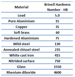
A convenient conversion is that of Brinell hardness to ultimate tensile strength. In this case, the ultimate tensile strength (in psi) approximately equals the Brinell Hardness Number multiplied by 500.

Brinell hardness test is one of indentation hardness tests, that has been developed for hardness testing. In Brinell tests, a hard, spherical indenter is forced under a specific load into the surface of the metal to be tested. The typical test uses a 10 mm (0.39 in) diameter  hardened steel ball as an indenter with a 3,000 kgf (29.42 kN; 6,614 lbf) force. The load is maintained constant for a specified time (between 10 and 30 s). For softer materials, a smaller force is used; for harder materials, a tungsten carbide ball is substituted for the steel ball.

Hardness and Tensile Strength

Besides the correlation between different hardness numbers, there are also some correlations possible with other material properties. For example, for heat-treated plain carbon steels and medium alloy steels, another convenient conversion is that of Brinell hardness to ultimate tensile strength. In this case, the ultimate tensile strength (in psi) approximately equals the Brinell Hardness Number multiplied by 500. Generally, a high hardness will indicate a relatively high strength and low ductility in the material.

In industry, hardness tests on metals are used mainly as a check on the quality and uniformity of metals, especially during heat treatment operations. The tests can generally be applied to the finished product without significant damage.

References:
Materials Science:
  1. U.S. Department of Energy, Material Science. DOE Fundamentals Handbook, Volume 1 and 2. January 1993.
  2. U.S. Department of Energy, Material Science. DOE Fundamentals Handbook, Volume 2 and 2. January 1993.
  3. William D. Callister, David G. Rethwisch. Materials Science and Engineering: An Introduction 9th Edition, Wiley; 9 edition (December 4, 2013), ISBN-13: 978-1118324578.
  4. Eberhart, Mark (2003). Why Things Break: Understanding the World by the Way It Comes Apart. Harmony. ISBN 978-1-4000-4760-4.
  5. Gaskell, David R. (1995). Introduction to the thermodynamics of Materials (4th ed.). Taylor and Francis Publishing. ISBN 978-1-56032-992-3.
  6. González-Viñas, W. & Mancini, H.L. (2004). An Introduction to Materials Science. Princeton University Press. ISBN 978-0-691-07097-1.
  7. Ashby, Michael; Hugh Shercliff; David Cebon (2007). Materials: engineering, science, processing and design (1st ed.). Butterworth-Heinemann. ISBN 978-0-7506-8391-3.
  8. J. R. Lamarsh, A. J. Baratta, Introduction to Nuclear Engineering, 3d ed., Prentice-Hall, 2001, ISBN: 0-201-82498-1.

See above:

Hardness

We hope, this article, Hardness and Tensile Strength, helps you. If so, give us a like in the sidebar. Main purpose of this website is to help the public to learn some interesting and important information about materials and their properties.
What is Knoop Hardness Test – Knoop Hardness Number – Definition

The Knoop hardness test method is one of microhardness tests – tests for mechanical hardness used particularly for very brittle materials or thin sheets, where only a small indentation may be made for testing purposes.

Indentation hardness measures the ability to withstand surface indentation (localized plastic deformation) and the resistance of a sample to material deformation due to a constant compression load from a sharp object. Tests for indentation hardness are primarily used in engineering and metallurgy fields. The traditional methods are based on well-defined physical indentation hardness tests. Very hard indenters of defined geometries and sizes are continuously pressed into the material under a particular force. Deformation parameters, such as the indentation depth in the Rockwell method, are recorded to give measures of hardness. Common indentation hardness scales are Brinell, Rockwell and Vickers.

See also: Hardness

Knoop Hardness Test

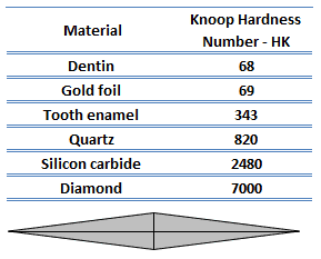
knoop hardness numbersThe Knoop hardness test method is one of microhardness tests – tests for mechanical hardness used particularly for very brittle materials or thin sheets, where only a small indentation may be made for testing purposes. The Knoop and Vickers techniques are referred to as microindentation-testing methods on the basis of indenter size. Both are well suited for measuring the hardness of small, selected specimen regions; furthermore, the Knoop technique is used for testing brittle materials such as ceramics. The geometry of this indenter is an extended pyramid with the length to width ratio being 7:1 and respective face angles are 172 degrees for the long edge and 130 degrees for the short edge.

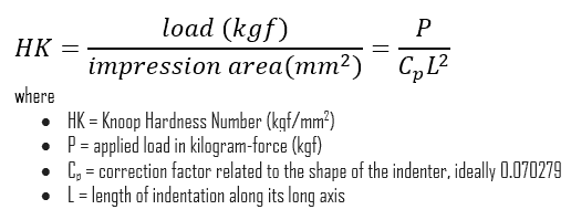
The Knoop and Vickers hardness numbers are designated by HK and HV, respectively, and hardness scales for both techniques are approximately equivalent. The Knoop hardness number HK or is given by the formula:

Knoop hardness number

See also: Brinell Hardness Test

See also: Rockwell Hardness Test

See also: Vickers Hardness Test

References:
Materials Science:
  1. U.S. Department of Energy, Material Science. DOE Fundamentals Handbook, Volume 1 and 2. January 1993.
  2. U.S. Department of Energy, Material Science. DOE Fundamentals Handbook, Volume 2 and 2. January 1993.
  3. William D. Callister, David G. Rethwisch. Materials Science and Engineering: An Introduction 9th Edition, Wiley; 9 edition (December 4, 2013), ISBN-13: 978-1118324578.
  4. Eberhart, Mark (2003). Why Things Break: Understanding the World by the Way It Comes Apart. Harmony. ISBN 978-1-4000-4760-4.
  5. Gaskell, David R. (1995). Introduction to the thermodynamics of Materials (4th ed.). Taylor and Francis Publishing. ISBN 978-1-56032-992-3.
  6. González-Viñas, W. & Mancini, H.L. (2004). An Introduction to Materials Science. Princeton University Press. ISBN 978-0-691-07097-1.
  7. Ashby, Michael; Hugh Shercliff; David Cebon (2007). Materials: engineering, science, processing and design (1st ed.). Butterworth-Heinemann. ISBN 978-0-7506-8391-3.
  8. J. R. Lamarsh, A. J. Baratta, Introduction to Nuclear Engineering, 3d ed., Prentice-Hall, 2001, ISBN: 0-201-82498-1.

See above:

Hardness

We hope, this article, Knoop Hardness Test – Knoop Hardness Number, helps you. If so, give us a like in the sidebar. Main purpose of this website is to help the public to learn some interesting and important information about materials and their properties.

What is Vickers Hardness Test – Vickers Hardness Number – Definition

The Vickers hardness test method can be also used as a microhardness test method, which is mostly used for small parts, thin sections, or case depth work.

Indentation hardness measures the ability to withstand surface indentation (localized plastic deformation) and the resistance of a sample to material deformation due to a constant compression load from a sharp object. Tests for indentation hardness are primarily used in engineering and metallurgy fields. The traditional methods are based on well-defined physical indentation hardness tests. Very hard indenters of defined geometries and sizes are continuously pressed into the material under a particular force. Deformation parameters, such as the indentation depth in the Rockwell method, are recorded to give measures of hardness. Common indentation hardness scales are Brinell, Rockwell and Vickers.

See also: Hardness

Vickers Hardness Test

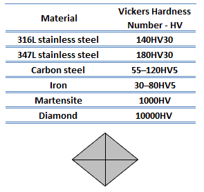
Vickers hardness testThe Vickers hardness test method was developed by Robert L. Smith and George E. Sandland at Vickers Ltd as an alternative to the Brinell method to measure the hardness of materials. The Vickers hardness test method can be also used as a microhardness test method, which is mostly used for small parts, thin sections, or case depth work. Since the test indentation is very small in a Vickers microhardness test, it is useful for a variety of applications such as: testing very thin materials like foils or measuring the surface of a part, small parts or small areas.

The Vickers method is based on an optical measurement system. The Microhardness test procedure, ASTM E-384, specifies a range of light loads using a diamond indenter to make an indentation which is measured and converted to a hardness value. The Vickers test is often easier to use than other hardness tests since the required calculations are independent of the size of the indenter, and the indenter can be used for all materials irrespective of hardness. A square base pyramid shaped diamond is used for testing in the Vickers scale. For microindentation typical loads are very light, ranging from 10gf to 1kgf, although macroindentation Vickers loads can range up to 30 kg or more.

See also: Brinell Hardness Test

See also: Rockwell Hardness Test

See also: Knoop Hardness Test

References:
Materials Science:
  1. U.S. Department of Energy, Material Science. DOE Fundamentals Handbook, Volume 1 and 2. January 1993.
  2. U.S. Department of Energy, Material Science. DOE Fundamentals Handbook, Volume 2 and 2. January 1993.
  3. William D. Callister, David G. Rethwisch. Materials Science and Engineering: An Introduction 9th Edition, Wiley; 9 edition (December 4, 2013), ISBN-13: 978-1118324578.
  4. Eberhart, Mark (2003). Why Things Break: Understanding the World by the Way It Comes Apart. Harmony. ISBN 978-1-4000-4760-4.
  5. Gaskell, David R. (1995). Introduction to the thermodynamics of Materials (4th ed.). Taylor and Francis Publishing. ISBN 978-1-56032-992-3.
  6. González-Viñas, W. & Mancini, H.L. (2004). An Introduction to Materials Science. Princeton University Press. ISBN 978-0-691-07097-1.
  7. Ashby, Michael; Hugh Shercliff; David Cebon (2007). Materials: engineering, science, processing and design (1st ed.). Butterworth-Heinemann. ISBN 978-0-7506-8391-3.
  8. J. R. Lamarsh, A. J. Baratta, Introduction to Nuclear Engineering, 3d ed., Prentice-Hall, 2001, ISBN: 0-201-82498-1.

See above:

Hardness

We hope, this article, Vickers Hardness Test – Vickers Hardness Number, helps you. If so, give us a like in the sidebar. Main purpose of this website is to help the public to learn some interesting and important information about materials and their properties.

What is Rockwell Hardness Number – Rockwell Scale – Definition

The Rockwell hardness number – HR is a result of the test to quantify the hardness of a material. The Rockwell hardness number – HR, can be directly displayed on the dial.

Indentation hardness measures the ability to withstand surface indentation (localized plastic deformation) and the resistance of a sample to material deformation due to a constant compression load from a sharp object. Tests for indentation hardness are primarily used in engineering and metallurgy fields. The traditional methods are based on well-defined physical indentation hardness tests. Very hard indenters of defined geometries and sizes are continuously pressed into the material under a particular force. Deformation parameters, such as the indentation depth in the Rockwell method, are recorded to give measures of hardness. Common indentation hardness scales are Brinell, Rockwell and Vickers.

See also: Hardness

Rockwell Hardness Number – Rockwell Scale

Rockwell hardness test is one of the most common indentation hardness tests, that has been developed for hardness testing. In contrast to Brinell test, the Rockwell tester measures the depth of penetration of an indenter under a large load (major load) compared to the penetration made by a preload (minor load). The minor load establishes the zero position. The major load is applied, then removed while still maintaining the minor load. The difference between depth of penetration before and after application of the major load is used to calculate the Rockwell hardness number. That is, the penetration depth and hardness are inversely proportional. The chief advantage of Rockwell hardness is its ability to display hardness values directly. The result is a dimensionless number noted as HRA, HRB, HRC, etc., where the last letter is the respective Rockwell scale.

Several different scales may be used from possible combinations of various indenters and different loads a process that permits the testing of virtually all metal alloys. The test provides results to quantify the hardness of a material, which is expressed by the Rockwell hardness number – HR, which is directly displayed on the dial. The various indenter types combined with a range of test loads form a matrix of Rockwell hardness scales that are applicable to a wide variety of materials. Rockwell B and Rockwell C are the typical tests in this facility. The Rockwell B penetrator is a 1.59mm (1/16 inch) diameter tungsten-carbide ball and the major load is 100kg. The Rockwell C test is performed with a Brale penetrator (120°diamond cone) and a major load of 150kg.

Each Rockwell hardness scale is identified by a letter designation indicative of the indenter type and the major and minor loads used for the test. The Rockwell hardness number is expressed as a combination of the measured numerical hardness value and the scale letter preceded by the letters, HR.

There are a variety of  hardness test methods in common use (e.g. Brinell, Knoop, Vickers and Rockwell). There are tables that are available correlating the hardness numbers from the different test methods   where correlation is applicable. In all scales, a high hardness number represents a hard metal.

In industry, hardness tests on metals are used mainly as a check on the quality and uniformity of metals, especially during heat treatment operations. The tests can generally be applied to the finished product without significant damage. Commercial popularity of the Rockwell hardness test arises from its speed, reliability, robustness, resolution and small area of indentation.

See also: Brinell Hardness Test

See also: Vickers Hardness Test

See also: Knoop Hardness Test

References:
Materials Science:
  1. U.S. Department of Energy, Material Science. DOE Fundamentals Handbook, Volume 1 and 2. January 1993.
  2. U.S. Department of Energy, Material Science. DOE Fundamentals Handbook, Volume 2 and 2. January 1993.
  3. William D. Callister, David G. Rethwisch. Materials Science and Engineering: An Introduction 9th Edition, Wiley; 9 edition (December 4, 2013), ISBN-13: 978-1118324578.
  4. Eberhart, Mark (2003). Why Things Break: Understanding the World by the Way It Comes Apart. Harmony. ISBN 978-1-4000-4760-4.
  5. Gaskell, David R. (1995). Introduction to the thermodynamics of Materials (4th ed.). Taylor and Francis Publishing. ISBN 978-1-56032-992-3.
  6. González-Viñas, W. & Mancini, H.L. (2004). An Introduction to Materials Science. Princeton University Press. ISBN 978-0-691-07097-1.
  7. Ashby, Michael; Hugh Shercliff; David Cebon (2007). Materials: engineering, science, processing and design (1st ed.). Butterworth-Heinemann. ISBN 978-0-7506-8391-3.
  8. J. R. Lamarsh, A. J. Baratta, Introduction to Nuclear Engineering, 3d ed., Prentice-Hall, 2001, ISBN: 0-201-82498-1.

See above:

Hardness

We hope, this article, Rockwell Hardness Number – Rockwell Scale, helps you. If so, give us a like in the sidebar. Main purpose of this website is to help the public to learn some interesting and important information about materials and their properties.

What is Rockwell Hardness Test – Definition

Rockwell hardness test is one of the most common indentation hardness tests, that has been developed for hardness testing. In contrast to Brinell test, the Rockwell tester measures the depth of penetration of an indenter under a large load (major load) compared to the penetration made by a preload (minor load).

Indentation hardness measures the ability to withstand surface indentation (localized plastic deformation) and the resistance of a sample to material deformation due to a constant compression load from a sharp object. Tests for indentation hardness are primarily used in engineering and metallurgy fields. The traditional methods are based on well-defined physical indentation hardness tests. Very hard indenters of defined geometries and sizes are continuously pressed into the material under a particular force. Deformation parameters, such as the indentation depth in the Rockwell method, are recorded to give measures of hardness. Common indentation hardness scales are Brinell, Rockwell and Vickers.

See also: Hardness

Rockwell Hardness Test

Rockwell hardness test is one of the most common indentation hardness tests, that has been developed for hardness testing. In contrast to Brinell test, the Rockwell tester measures the depth of penetration of an indenter under a large load (major load) compared to the penetration made by a preload (minor load). The minor load establishes the zero position. The major load is applied, then removed while still maintaining the minor load. The difference between depth of penetration before and after application of the major load is used to calculate the Rockwell hardness number. That is, the penetration depth and hardness are inversely proportional. The chief advantage of Rockwell hardness is its ability to display hardness values directly. The result is a dimensionless number noted as HRA, HRB, HRC, etc., where the last letter is the respective Rockwell scale.

Several different scales may be used from possible combinations of various indenters and different loads a process that permits the testing of virtually all metal alloys. The test provides results to quantify the hardness of a material, which is expressed by the Rockwell hardness number – HR, which is directly displayed on the dial. The various indenter types combined with a range of test loads form a matrix of Rockwell hardness scales that are applicable to a wide variety of materials. Rockwell B and Rockwell C are the typical tests in this facility. The Rockwell B penetrator is a 1.59mm (1/16 inch) diameter tungsten-carbide ball and the major load is 100kg. The Rockwell C test is performed with a Brale penetrator (120°diamond cone) and a major load of 150kg.

Each Rockwell hardness scale is identified by a letter designation indicative of the indenter type and the major and minor loads used for the test. The Rockwell hardness number is expressed as a combination of the measured numerical hardness value and the scale letter preceded by the letters, HR.

There are a variety of  hardness test methods in common use (e.g. Brinell, Knoop, Vickers and Rockwell). There are tables that are available correlating the hardness numbers from the different test methods   where correlation is applicable. In all scales, a high hardness number represents a hard metal.

In industry, hardness tests on metals are used mainly as a check on the quality and uniformity of metals, especially during heat treatment operations. The tests can generally be applied to the finished product without significant damage. Commercial popularity of the Rockwell hardness test arises from its speed, reliability, robustness, resolution and small area of indentation.

See also: Brinell Hardness Test

See also: Vickers Hardness Test

See also: Knoop Hardness Test

References:
Materials Science:
  1. U.S. Department of Energy, Material Science. DOE Fundamentals Handbook, Volume 1 and 2. January 1993.
  2. U.S. Department of Energy, Material Science. DOE Fundamentals Handbook, Volume 2 and 2. January 1993.
  3. William D. Callister, David G. Rethwisch. Materials Science and Engineering: An Introduction 9th Edition, Wiley; 9 edition (December 4, 2013), ISBN-13: 978-1118324578.
  4. Eberhart, Mark (2003). Why Things Break: Understanding the World by the Way It Comes Apart. Harmony. ISBN 978-1-4000-4760-4.
  5. Gaskell, David R. (1995). Introduction to the thermodynamics of Materials (4th ed.). Taylor and Francis Publishing. ISBN 978-1-56032-992-3.
  6. González-Viñas, W. & Mancini, H.L. (2004). An Introduction to Materials Science. Princeton University Press. ISBN 978-0-691-07097-1.
  7. Ashby, Michael; Hugh Shercliff; David Cebon (2007). Materials: engineering, science, processing and design (1st ed.). Butterworth-Heinemann. ISBN 978-0-7506-8391-3.
  8. J. R. Lamarsh, A. J. Baratta, Introduction to Nuclear Engineering, 3d ed., Prentice-Hall, 2001, ISBN: 0-201-82498-1.

See above:

Hardness

We hope, this article, Rockwell Hardness Test, helps you. If so, give us a like in the sidebar. Main purpose of this website is to help the public to learn some interesting and important information about materials and their properties.

What is Brinell Hardness Number – Brinell Scale – Definition

The Brinell hardness number (HB) is the load divided by the surface area of the indentation. The diameter of the impression is measured with a microscope with a superimposed scale.

Indentation hardness measures the ability to withstand surface indentation (localized plastic deformation) and the resistance of a sample to material deformation due to a constant compression load from a sharp object. Tests for indentation hardness are primarily used in engineering and metallurgy fields. The traditional methods are based on well-defined physical indentation hardness tests. Very hard indenters of defined geometries and sizes are continuously pressed into the material under a particular force. Deformation parameters, such as the indentation depth in the Rockwell method, are recorded to give measures of hardness. Common indentation hardness scales are Brinell, Rockwell and Vickers.

See also: Hardness

Brinell Hardness Number – Brinell Scale

Brinell hardness test is one of indentation hardness tests, that has been developed for hardness testing. In Brinell tests, a hard, spherical indenter is forced under a specific load into the surface of the metal to be tested. The typical test uses a 10 mm (0.39 in) diameter  hardened steel ball as an indenter with a 3,000 kgf (29.42 kN; 6,614 lbf) force. The load is maintained constant for a specified time (between 10 and 30 s). For softer materials, a smaller force is used; for harder materials, a tungsten carbide ball is substituted for the steel ball.

The test provides numerical results to quantify the hardness of a material, which is expressed by the Brinell hardness number – HB. The Brinell hardness number is designated by the most commonly used test standards (ASTM E10-14[2] and ISO 6506–1:2005) as HBW (H from hardness, B from brinell and W from the material of the indenter, tungsten (wolfram) carbide). In former standards HB or HBS were used to refer to measurements made with steel indenters.

&nbsp;

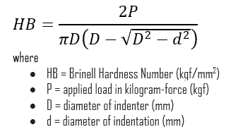
The Brinell hardness number (HB) is the load divided by the surface area of the indentation. The diameter of the impression is measured with a microscope with a superimposed scale. The Brinell hardness number is computed from the equation:

Brinell hardness test

There are a variety of  test methods in common use (e.g. Brinell, Knoop, Vickers and Rockwell). There are tables that are available correlating the hardness numbers from the different test methods where correlation is applicable. In all scales, a high hardness number represents a hard metal.

Brinell hardness numberBesides the correlation between different hardness numbers, there are also some correlations possible with other material properties. For example, for heat-treated plain carbon steels and medium alloy steels, another convenient conversion is that of Brinell hardness to ultimate tensile strength. In this case, the ultimate tensile strength (in psi) approximately equals the Brinell Hardness Number multiplied by 500. Generally, a high hardness will indicate a relatively high strength and low ductility in the material.

In industry, hardness tests on metals are used mainly as a check on the quality and uniformity of metals, especially during heat treatment operations. The tests can generally be applied to the finished product without significant damage.

See also: Rockwell Hardness Test

See also: Vickers Hardness Test

See also: Knoop Hardness Test

References:
Materials Science:
  1. U.S. Department of Energy, Material Science. DOE Fundamentals Handbook, Volume 1 and 2. January 1993.
  2. U.S. Department of Energy, Material Science. DOE Fundamentals Handbook, Volume 2 and 2. January 1993.
  3. William D. Callister, David G. Rethwisch. Materials Science and Engineering: An Introduction 9th Edition, Wiley; 9 edition (December 4, 2013), ISBN-13: 978-1118324578.
  4. Eberhart, Mark (2003). Why Things Break: Understanding the World by the Way It Comes Apart. Harmony. ISBN 978-1-4000-4760-4.
  5. Gaskell, David R. (1995). Introduction to the thermodynamics of Materials (4th ed.). Taylor and Francis Publishing. ISBN 978-1-56032-992-3.
  6. González-Viñas, W. & Mancini, H.L. (2004). An Introduction to Materials Science. Princeton University Press. ISBN 978-0-691-07097-1.
  7. Ashby, Michael; Hugh Shercliff; David Cebon (2007). Materials: engineering, science, processing and design (1st ed.). Butterworth-Heinemann. ISBN 978-0-7506-8391-3.
  8. J. R. Lamarsh, A. J. Baratta, Introduction to Nuclear Engineering, 3d ed., Prentice-Hall, 2001, ISBN: 0-201-82498-1.

See above:

Hardness

We hope, this article, Brinell Hardness Number – Brinell Scale, helps you. If so, give us a like in the sidebar. Main purpose of this website is to help the public to learn some interesting and important information about materials and their properties.