About Lead
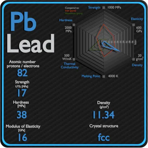
Lead is a heavy metal that is denser than most common materials. Lead is soft and malleable, and has a relatively low melting point. Lead is widely used as a gamma shield. Major advantage of lead shield is in its compactness due to its higher density. Lead has the highest atomic number of any stable element and concludes three major decay chains of heavier elements.
Strength of Lead
In mechanics of materials, the strength of a material is its ability to withstand an applied load without failure or plastic deformation. Strength of materials basically considers the relationship between the external loads applied to a material and the resulting deformation or change in material dimensions. In designing structures and machines, it is important to consider these factors, in order that the material selected will have adequate strength to resist applied loads or forces and retain its original shape. Strength of a material is its ability to withstand this applied load without failure or plastic deformation.
For tensile stress, the capacity of a material or structure to withstand loads tending to elongate is known as ultimate tensile strength (UTS). Yield strength or yield stress is the material property defined as the stress at which a material begins to deform plastically whereas yield point is the point where nonlinear (elastic + plastic) deformation begins.
Ultimate Tensile Strength of Lead
Ultimate tensile strength of Lead is 17 MPa.
Yield Strength of Lead
Yield strength of Lead is 5.5 MPa.
Modulus of Elasticity of Lead
The Young’s modulus of elasticity of Lead is 5.5 MPa.
The shear modulus of elasticity of Lead is 5.6 GPa.
The bulk modulus of elasticity of Lead is 46 GPa.
Hardness of Lead
In materials science, hardness is the ability to withstand surface indentation (localized plastic deformation) and scratching. Brinell hardness test is one of indentation hardness tests, that has been developed for hardness testing. In Brinell tests, a hard, spherical indenter is forced under a specific load into the surface of the metal to be tested.
Brinell hardness of Lead is approximately 38 MPa.
The Vickers hardness test method was developed by Robert L. Smith and George E. Sandland at Vickers Ltd as an alternative to the Brinell method to measure the hardness of materials. The Vickers hardness test method can be also used as a microhardness test method, which is mostly used for small parts, thin sections, or case depth work.
Vickers hardness of Lead is approximately N/A.
Scratch hardness is the measure of how resistant a sample is to permanent plastic deformation due to friction from a sharp object. The most common scale for this qualitative test is Mohs scale, which is used in mineralogy. The Mohs scale of mineral hardness is based on the ability of one natural sample of mineral to scratch another mineral visibly.
Lead is has a hardness of approximately 1.5.
Lead – Crystal Structure
A possible crystal structure of Lead is face-centered cubic structure.
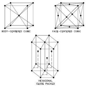
In metals, and in many other solids, the atoms are arranged in regular arrays called crystals. A crystal lattice is a repeating pattern of mathematical points that extends throughout space. The forces of chemical bonding causes this repetition. It is this repeated pattern which control properties like strength, ductility, density, conductivity (property of conducting or transmitting heat, electricity, etc.), and shape. There are 14 general types of such patterns known as Bravais lattices.
Crystal Structure of Lead

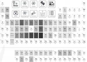
Strength of Elements
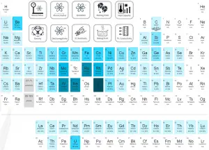
Elasticity of Elements
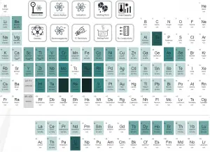
Hardness of Elements
About Strength
 In mechanics of materials, the strength of a material is its ability to withstand an applied load without failure or plastic deformation. Strength of materials basically considers the relationship between the external loads applied to a material and the resulting deformation or change in material dimensions. In designing structures and machines, it is important to consider these factors, in order that the material selected will have adequate strength to resist applied loads or forces and retain its original shape. Strength of a material is its ability to withstand this applied load without failure or plastic deformation.
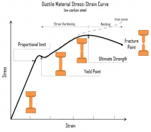
A schematic diagram for the stress-strain curve of low carbon steel at room temperature is shown in the figure. There are several stages showing different behaviors, which suggests different mechanical properties. To clarify, materials can miss one or more stages shown in the figure, or have totally different stages. In this case we have to distinguish between stress-strain characteristics of ductile and brittle materials. The following points describe the different regions of the stress-strain curve and the importance of several specific locations.
- Proportional limit. The proportional limit corresponds to the location of stress at the end of the linear region, so the stress-strain graph is a straight line, and the gradient will be equal to the elastic modulus of the material. For tensile and compressive stress, the slope of the portion of the curve where stress is proportional to strain is referred to as Young’s modulus and Hooke’s Law applies. Between the proportional limit and the yield point the Hooke’s Law becomes questionable between and strain increases more rapidly.
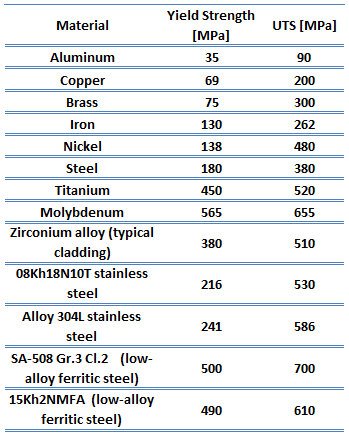 Yield point. The yield point is the point on a stress-strain curve that indicates the limit of elastic behavior and the beginning plastic behavior. Yield strength or yield stress is the material property defined as the stress at which a material begins to deform plastically whereas yield point is the point where nonlinear (elastic + plastic) deformation begins. Prior to the yield point, the material will deform elastically and will return to its original shape when the applied stress is removed. Once the yield point is passed, some fraction of the deformation will be permanent and non-reversible. Some steels and other materials exhibit a behaviour termed a yield point phenomenon. Yield strengths vary from 35 MPa for a low-strength aluminum to greater than 1400 MPa for very high-strength steels.
- Ultimate tensile strength. The ultimate tensile strength is the maximum on the engineering stress-strain curve. This corresponds to the maximum stress that can be sustained by a structure in tension. Ultimate tensile strength is often shortened to “tensile strength” or even to “the ultimate.” If this stress is applied and maintained, fracture will result. Often, this value is significantly more than the yield stress (as much as 50 to 60 percent more than the yield for some types of metals). When a ductile material reaches its ultimate strength, it experiences necking where the cross-sectional area reduces locally. The stress-strain curve contains no higher stress than the ultimate strength. Even though deformations can continue to increase, the stress usually decreases after the ultimate strength has been achieved. It is an intensive property; therefore its value does not depend on the size of the test specimen. However, it is dependent on other factors, such as the preparation of the specimen, the presence or otherwise of surface defects, and the temperature of the test environment and material. Ultimate tensile strengths vary from 50 MPa for an aluminum to as high as 3000 MPa for very high-strength steels.
- Fracture point: The fracture point is the point of strain where the material physically separates. At this point, the strain reaches its maximum value and the material actually fractures, even though the corresponding stress may be less than the ultimate strength at this point. Ductile materials have a fracture strength lower than the ultimate tensile strength (UTS), whereas in brittle materials the fracture strength is equivalent to the UTS. If a ductile material reaches its ultimate tensile strength in a load-controlled situation, it will continue to deform, with no additional load application, until it ruptures. However, if the loading is displacement-controlled, the deformation of the material may relieve the load, preventing rupture.
About Modulus of Elasticity
In case of tensional stress of a uniform bar (stress-strain curve), the Hooke’s law describes behaviour of a bar in the elastic region. In this region, the elongation of the bar is directly proportional to the tensile force and the length of the bar and inversely proportional to the cross-sectional area and the modulus of elasticity. Up to a limiting stress, a body will be able to recover its dimensions on removal of the load. The applied stresses cause the atoms in a crystal to move from their equilibrium position. All the atoms are displaced the same amount and still maintain their relative geometry. When the stresses are removed, all the atoms return to their original positions and no permanent deformation occurs. According to the Hooke’s law, the stress is proportional to the strain (in the elastic region), and the slope is Young’s modulus.
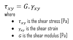
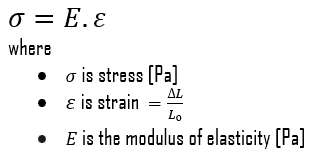 We can extend the same idea of relating stress to strain to shear applications in the linear region, relating shear stress to shear strain to create Hooke’s law for shear stress:
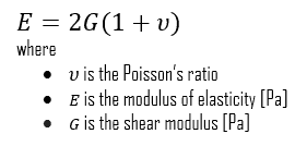
For isotropic materials within the elastic region, you can relate Poisson’s ratio (ν), Young’s modulus of elasticity (E), and the shear modulus of elasticity (G):
The elastic moduli relevant to polycrystalline materials:
- Young’s Modulus of Elasticity. The Young’s modulus of elasticity is the elastic modulus for tensile and compressive stress in the linear elasticity regime of a uniaxial deformation and is usually assessed by tensile tests.
- Shear Modulus of Elasticity. The shear modulus, or the modulus of rigidity, is derived from the torsion of a cylindrical test piece. It describes the material’s response to shear stress. Its symbol is G. The shear modulus is one of several quantities for measuring the stiffness of materials and it arises in the generalized Hooke’s law.
- Bulk Modulus of Elasticity. The bulk modulus of elasticity is describes volumetric elasticity, or the tendency of an object to deform in all directions when uniformly loaded in all directions. For example, it describes the elastic response to hydrostatic pressure and equilateral tension (like the pressure at the bottom of the ocean or a deep swimming pool). It is also the property of a material that determines the elastic response to the application of stress. For a fluid, only the bulk modulus is meaningful.
About Hardness
In materials science, hardness is the ability to withstand surface indentation (localized plastic deformation) and scratching. Hardness is probably the most poorly defined material property because it may indicate resistance to scratching, resistance to abrasion, resistance to indentation or even resistance to shaping or localized plastic deformation. Hardness is important from an engineering standpoint because resistance to wear by either friction or erosion by steam, oil, and water generally increases with hardness.
There are three main types of hardness measurements:
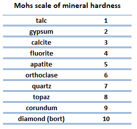 Scratch hardness. Scratch hardness is the measure of how resistant a sample is to permanent plastic deformation due to friction from a sharp object. The most common scale for this qualitative test is Mohs scale, which is used in mineralogy. The Mohs scale of mineral hardness is based on the ability of one natural sample of mineral to scratch another mineral visibly. The hardness of a material is measured against the scale by finding the hardest material that the given material can scratch, or the softest material that can scratch the given material. For example, if some material is scratched by topaz but not by quartz, its hardness on the Mohs scale would fall between 7 and 8.
- Indentation hardness. Indentation hardness measures the ability to withstand surface indentation (localized plastic deformation) and the resistance of a sample to material deformation due to a constant compression load from a sharp object. Tests for indentation hardness are primarily used in engineering and metallurgy fields. The traditional methods are based on well-defined physical indentation hardness tests. Very hard indenters of defined geometries and sizes are continuously pressed into the material under a particular force. Deformation parameters, such as the indentation depth in the Rockwell method, are recorded to give measures of hardness. Common indentation hardness scales are Brinell, Rockwell and Vickers.
- Rebound hardness. Rebound hardness, also known as dynamic hardness, measures the height of the “bounce” of a diamond-tipped hammer dropped from a fixed height onto a material. One of devices used to take this measurement is known as a scleroscope. It consists of a steel ball dropped from a fixed height. This type of hardness is related to elasticity.
About Crystal Structure
The three most common basic crystal patterns are:
- bcc. In a bcc (BCC) arrangement of atoms, the unit cell consists of eight atoms at the corners of a cube and one atom at the body center of the cube. In a bcc arrangement, a unit cell contains (8 corner atoms × ⅛) + (1 center atom × 1) = 2 atoms. The packing is more efficient (68%) than simple cubic and the structure is a common one for alkali metals and early transition metals. Metals containing BCC structures include ferrite, chromium, vanadium, molybdenum, and tungsten. These metals possess high strength and low ductility.
- fcc.In a fcc (FCC) arrangement of atoms, the unit cell consists of eight atoms at the corners of a cube and one atom at the center of each of the faces of the cube. In a fcc arrangement, a unit cell contains (8 corner atoms × ⅛) + (6 face atoms × ½) = 4 atoms. This structure, along with its hexagonal relative (hcp), has the most efficient packing (74%). Metals containing FCC structures include austenite, aluminum, copper, lead, silver, gold, nickel, platinum, and thorium. These metals possess low strength and high ductility.
- hcp. In a hcp (HCP) arrangement of atoms, the unit cell consists of three layers of atoms. The top and bottom layers contain six atoms at the corners of a hexagon and one atom at the center of each hexagon. The middle layer contains three atoms nestled between the atoms of the top and bottom layers, hence, the name close-packed. Hexagonal close packed (hcp) is one of the two simple types of atomic packing with the highest density, the other being the face centered cubic (fcc). However, unlike the fcc, it is not a Bravais lattice as there are two nonequivalent sets of lattice points. Metals containing HCP structures include beryllium, magnesium, zinc, cadmium, cobalt, thallium, and zirconium. HCP metals are not as ductile as FCC metals.
Summary
| Element |
Lead |
| Ultimate Tensile Strength |
17 MPa |
| Yield Strength |
5.5 MPa |
| Young’s Modulus of Elasticity |
16 GPa |
| Shear Modulus of Elasticity |
5.6 GPa |
| Bulk Modulus of Elasticity |
46 GPa |
| Mohs Scale |
1.5 |
| Brinell Hardness |
38 MPa |
| Vickers Hardness |
N/A |
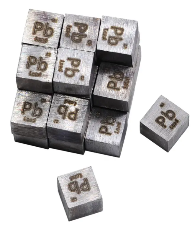
Source: www.luciteria.com
Properties of other elements


