About Tool Steel

Tool steel refers to a variety of carbon and alloy steels that are particularly well-suited to be made into tools (punches, dies, molds, tools for cutting, blanking, forming, drawing, steering and slitting tools). Their suitability comes from their distinctive hardness, resistance to abrasion and deformation, and their ability to hold a cutting edge at elevated temperatures. With a carbon content between 0.5% and 1.5%, tool steels are manufactured under carefully controlled conditions to produce the required quality. The presence of carbides in their matrix plays the dominant role in the qualities of tool steel.
They are generally grouped into two classes:
- Plain carbon steels containing a high percentage of carbon, about 0.80-1.50%
- Alloy tool steels, in which other elements (chromium, molybdenum, vanadium, tungsten and cobalt) are added to provide greater strength, toughness, corrosion and heat resistance of steel.
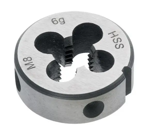
One of subgroups of tool steels is high-speed steels (HSS), which were named primarily for their ability to machine and cut materials at high speeds (high hot hardness). It is often used in power-saw blades and drill bits. This group of tool steels is described in a separate article.
Alloying Agents in Alloy Tool Steels
Pure iron is too soft to be used for the purpose of structure, but the addition of small quantities of other elements (carbon, manganese or silicon for instance) greatly increases its mechanical strength. The synergistic effect of alloying elements and heat treatment produces a tremendous variety of microstructures and properties. The four major alloying elements that form carbides in tool and die steel are: tungsten, chromium, vanadium and molybdenum. These alloying elements combine with carbon to form very hard and wear-resistant carbide compounds.
- Tungsten. Produces stable carbides and refines grain size so as to increase hardness, particularly at high temperatures. Tungsten is used extensively in high-speed tool steels and has been proposed as a substitute for molybdenum in reduced-activation ferritic steels for nuclear applications.
- Chromium. Chromium increases hardness, strength, and corrosion resistance. The strengthening effect of forming stable metal carbides at the grain boundaries and the strong increase in corrosion resistance made chromium an important alloying material for steel. Generally speaking, the concentration specified for most grades is approximately 4%. This level appears to result in the best balance between hardness and toughness. Chromium plays an important role in the hardening mechanism and is considered irreplaceable. At higher temperatures, chromium contributes increased strength. It is ordinarily used for applications of this nature in conjunction with molybdenum.
- Molybdenum. Molybdenum (about 0.50-8.00%) when added to a tool steel makes it more resistant to high temperature. Molybdenum increases hardenability and strength, particularly at high temperatures due to the high melting point of molybdenum. Molybdenum is unique in the extent to which it increases the high-temperature tensile and creep strengths of steel. It retards the transformation of austenite to pearlite far more than it does the transformation of austenite to bainite; thus, bainite may be produced by continuous cooling of molybdenum-containing steels.
- Vanadium. Vanadium is generally added to steel to inhibit grain growth during heat treatment. In controlling grain growth, it improves both the strength and toughness of hardened and tempered steels. The size of the grain determines the properties of the metal. For example, smaller grain size increases tensile strength and tends to increase ductility. A larger grain size is preferred for improved high-temperature creep properties.
Example of Tool Steel – A2 Steel
A2 tool steel is an air hardening, cold work steel of group A steels containing molybdenum and chromium. A2 steel contains 5% of chromium steel which provides high hardness after heat treatment with good dimensional stability. The carbon content in A2 tool steels is high. A2 offers good toughness with medium wear resistance and is relatively easy to machine. A2 tool steel can be used in many applications which require good wear resistance as well as good toughness.
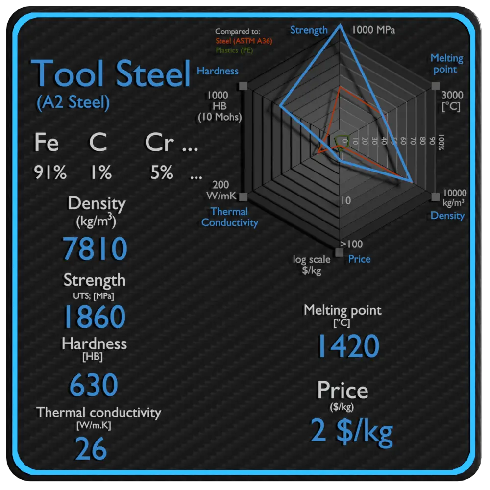
Summary
| Name | Tool Steel |
| Phase at STP | solid |
| Density | 7810 kg/m3 |
| Ultimate Tensile Strength | 1860 MPa |
| Yield Strength | 1400 MPa |
| Young’s Modulus of Elasticity | 200 GPa |
| Brinell Hardness | 630 BHN |
| Melting Point | 1420 °C |
| Thermal Conductivity | 26 W/mK |
| Heat Capacity | 465 J/g K |
| Price | 2 $/kg |
Density of Tool Steel
Typical densities of various substances are at atmospheric pressure. Density is defined as the mass per unit volume. It is an intensive property, which is mathematically defined as mass divided by volume: ρ = m/V
In words, the density (ρ) of a substance is the total mass (m) of that substance divided by the total volume (V) occupied by that substance. The standard SI unit is kilograms per cubic meter (kg/m3). The Standard English unit is pounds mass per cubic foot (lbm/ft3).
Density of Tool Steel is 7810 kg/m3.
Example: Density
Calculate the height of a cube made of Tool Steel, which weighs one metric ton.
Solution:
Density is defined as the mass per unit volume. It is mathematically defined as mass divided by volume: ρ = m/V
As the volume of a cube is the third power of its sides (V = a3), the height of this cube can be calculated:
The height of this cube is then a = 0.504 m.
Density of Materials

Mechanical Properties of Tool Steel – A2 Steel
Materials are frequently chosen for various applications because they have desirable combinations of mechanical characteristics. For structural applications, material properties are crucial and engineers must take them into account.
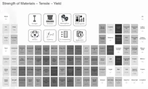
Strength of Tool Steel – A2 Steel
In mechanics of materials, the strength of a material is its ability to withstand an applied load without failure or plastic deformation. Strength of materials basically considers the relationship between the external loads applied to a material and the resulting deformation or change in material dimensions. Strength of a material is its ability to withstand this applied load without failure or plastic deformation.
Ultimate Tensile Strength
Ultimate tensile strength of tool steel – A2 steel depends on heat treatment process, but it is about 1860 MPa.
 The ultimate tensile strength is the maximum on the engineering stress-strain curve. This corresponds to the maximum stress that can be sustained by a structure in tension. Ultimate tensile strength is often shortened to “tensile strength” or even to “the ultimate.” If this stress is applied and maintained, fracture will result. Often, this value is significantly more than the yield stress (as much as 50 to 60 percent more than the yield for some types of metals). When a ductile material reaches its ultimate strength, it experiences necking where the cross-sectional area reduces locally. The stress-strain curve contains no higher stress than the ultimate strength. Even though deformations can continue to increase, the stress usually decreases after the ultimate strength has been achieved. It is an intensive property; therefore its value does not depend on the size of the test specimen. However, it is dependent on other factors, such as the preparation of the specimen, the presence or otherwise of surface defects, and the temperature of the test environment and material. Ultimate tensile strengths vary from 50 MPa for an aluminum to as high as 3000 MPa for very high-strength steels.
Yield Strength
Yield strength of tool steel – A2 steel depends on heat treatment process, but it is about 1400 MPa.
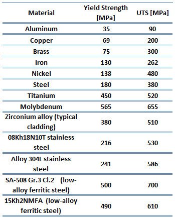
The yield point is the point on a stress-strain curve that indicates the limit of elastic behavior and the beginning plastic behavior. Yield strength or yield stress is the material property defined as the stress at which a material begins to deform plastically whereas yield point is the point where nonlinear (elastic + plastic) deformation begins. Prior to the yield point, the material will deform elastically and will return to its original shape when the applied stress is removed. Once the yield point is passed, some fraction of the deformation will be permanent and non-reversible. Some steels and other materials exhibit a behaviour termed a yield point phenomenon. Yield strengths vary from 35 MPa for a low-strength aluminum to greater than 1400 MPa for very high-strength steels.
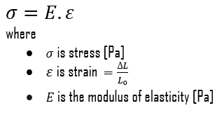
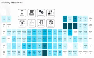
Young’s Modulus of Elasticity
Young’s modulus of elasticity of tool steel – A2 steel is 200 GPa.
The Young’s modulus of elasticity is the elastic modulus for tensile and compressive stress in the linear elasticity regime of a uniaxial deformation and is usually assessed by tensile tests. Up to a limiting stress, a body will be able to recover its dimensions on removal of the load. The applied stresses cause the atoms in a crystal to move from their equilibrium position. All the atoms are displaced the same amount and still maintain their relative geometry. When the stresses are removed, all the atoms return to their original positions and no permanent deformation occurs. According to the Hooke’s law, the stress is proportional to the strain (in the elastic region), and the slope is Young’s modulus. Young’s modulus is equal to the longitudinal stress divided by the strain.
Hardness of Tool Steel – A2 Steel
Rockwell hardness of tool steel – A2 steel depends on heat treatment process, but it is approximately 60 HRC.
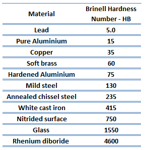
Rockwell hardness test is one of the most common indentation hardness tests, that has been developed for hardness testing. In contrast to Brinell test, the Rockwell tester measures the depth of penetration of an indenter under a large load (major load) compared to the penetration made by a preload (minor load). The minor load establishes the zero position. The major load is applied, then removed while still maintaining the minor load. The difference between depth of penetration before and after application of the major load is used to calculate the Rockwell hardness number. That is, the penetration depth and hardness are inversely proportional. The chief advantage of Rockwell hardness is its ability to display hardness values directly. The result is a dimensionless number noted as HRA, HRB, HRC, etc., where the last letter is the respective Rockwell scale.
The Rockwell C test is performed with a Brale penetrator (120°diamond cone) and a major load of 150kg.
Example: Strength
Assume a plastic rod, which is made of Tool Steel. This plastic rod has a cross-sectional area of 1 cm2. Calculate the tensile force needed to achieve the ultimate tensile strength for this material, which is: UTS = 1860 MPa.
Solution:
Stress (σ) can be equated to the load per unit area or the force (F) applied per cross-sectional area (A) perpendicular to the force as:

therefore, the tensile force needed to achieve the ultimate tensile strength is:
F = UTS x A = 1860 x 106 x 0.0001 = 186 000 N
Strength of Materials
Elasticity of Materials
Hardness of Materials

Thermal Properties of Tool Steel – A2 Steel
Thermal properties of materials refer to the response of materials to changes in their thermodynamics/thermodynamic-properties/what-is-temperature-physics/”>temperature and to the application of heat. As a solid absorbs thermodynamics/what-is-energy-physics/”>energy in the form of heat, its temperature rises and its dimensions increase. But different materials react to the application of heat differently.
Heat capacity, thermal expansion, and thermal conductivity are properties that are often critical in the practical use of solids.
Melting Point of Tool Steel – A2 Steel
Melting point of tool steel – A2 steel is around 1420°C.
In general, melting is a phase change of a substance from the solid to the liquid phase. The melting point of a substance is the temperature at which this phase change occurs. The melting point also defines a condition in which the solid and liquid can exist in equilibrium.
Thermal Conductivity of Tool Steel – A2 Steel
The thermal conductivity of tool steel – A2 steel is 26 W/(m.K).
The heat transfer characteristics of a solid material are measured by a property called the thermal conductivity, k (or λ), measured in W/m.K. It is a measure of a substance’s ability to transfer heat through a material by conduction. Note that Fourier’s law applies for all matter, regardless of its state (solid, liquid, or gas), therefore, it is also defined for liquids and gases.
The thermal conductivity of most liquids and solids varies with temperature. For vapors, it also depends upon pressure. In general:
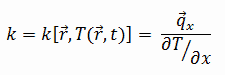
Most materials are very nearly homogeneous, therefore we can usually write k = k (T). Similar definitions are associated with thermal conductivities in the y- and z-directions (ky, kz), but for an isotropic material the thermal conductivity is independent of the direction of transfer, kx = ky = kz = k.
Example: Heat transfer calculation
 Thermal conductivity is defined as the amount of heat (in watts) transferred through a square area of material of given thickness (in metres) due to a difference in temperature. The lower the thermal conductivity of the material the greater the material’s ability to resist heat transfer.
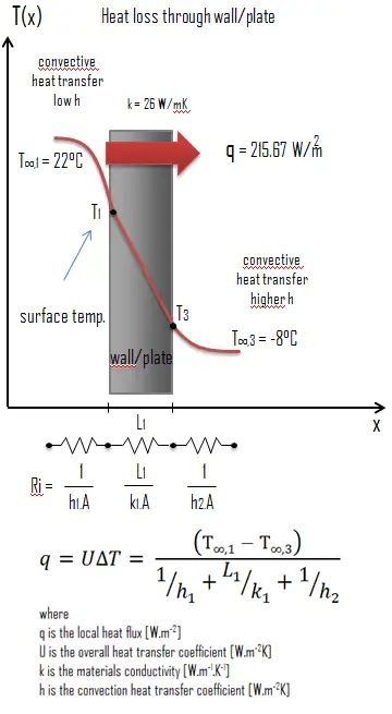
Calculate the rate of heat flux through a wall 3 m x 10 m in area (A = 30 m2). The wall is 15 cm thick (L1) and it is made of Tool Steel with the thermal conductivity of k1 = 26 W/m.K (poor thermal insulator). Assume that, the indoor and the outdoor temperatures are 22°C and -8°C, and the convection heat transfer coefficients on the inner and the outer sides are h1 = 10 W/m2K and h2 = 30 W/m2K, respectively. Note that, these convection coefficients strongly depend especially on ambient and interior conditions (wind, humidity, etc.).
Calculate the heat flux (heat loss) through this wall.
Solution:
As was written, many of the heat transfer processes involve composite systems and even involve a combination of both conduction and convection. With these composite systems, it is often convenient to work with an overall heat transfer coefficient, known as a U-factor. The U-factor is defined by an expression analogous to Newton’s law of cooling:
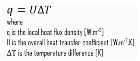
The overall heat transfer coefficient is related to the total thermal resistance and depends on the geometry of the problem.
Assuming one-dimensional heat transfer through the plane wall and disregarding radiation, the overall heat transfer coefficient can be calculated as:
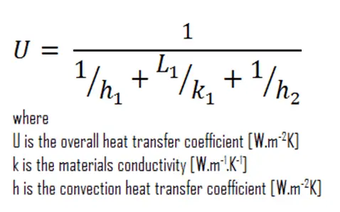
The overall heat transfer coefficient is then: U = 1 / (1/10 + 0.15/26 + 1/30) = 7.19 W/m2K
The heat flux can be then calculated simply as: q = 7.19 [W/m2K] x 30 [K] = 215.67 W/m2
The total heat loss through this wall will be: qloss = q . A = 215.67 [W/m2] x 30 [m2] = 6470.05 W
Melting Point of Materials

Thermal Conductivity of Materials
Heat Capacity of Materials