About Invar
Invar is an alloy of nickel and iron. This alloy is also known generically as FeNi36 (64FeNi in the US). Invar is notable for its uniquely low coefficient of thermal expansion (CTE or α). The name Invar comes from the word invariable, referring to its relative lack of expansion or contraction with temperature changes. Invar has a near-zero coefficient of thermal expansion, making it useful in constructing precision instruments whose dimensions need to remain constant in spite of varying temperature. The discovery of the alloy was made in 1896 by Swiss physicist Charles Édouard Guillaume for which he received the Nobel Prize in Physics in 1920.

Summary
| Name | Invar |
| Phase at STP | solid |
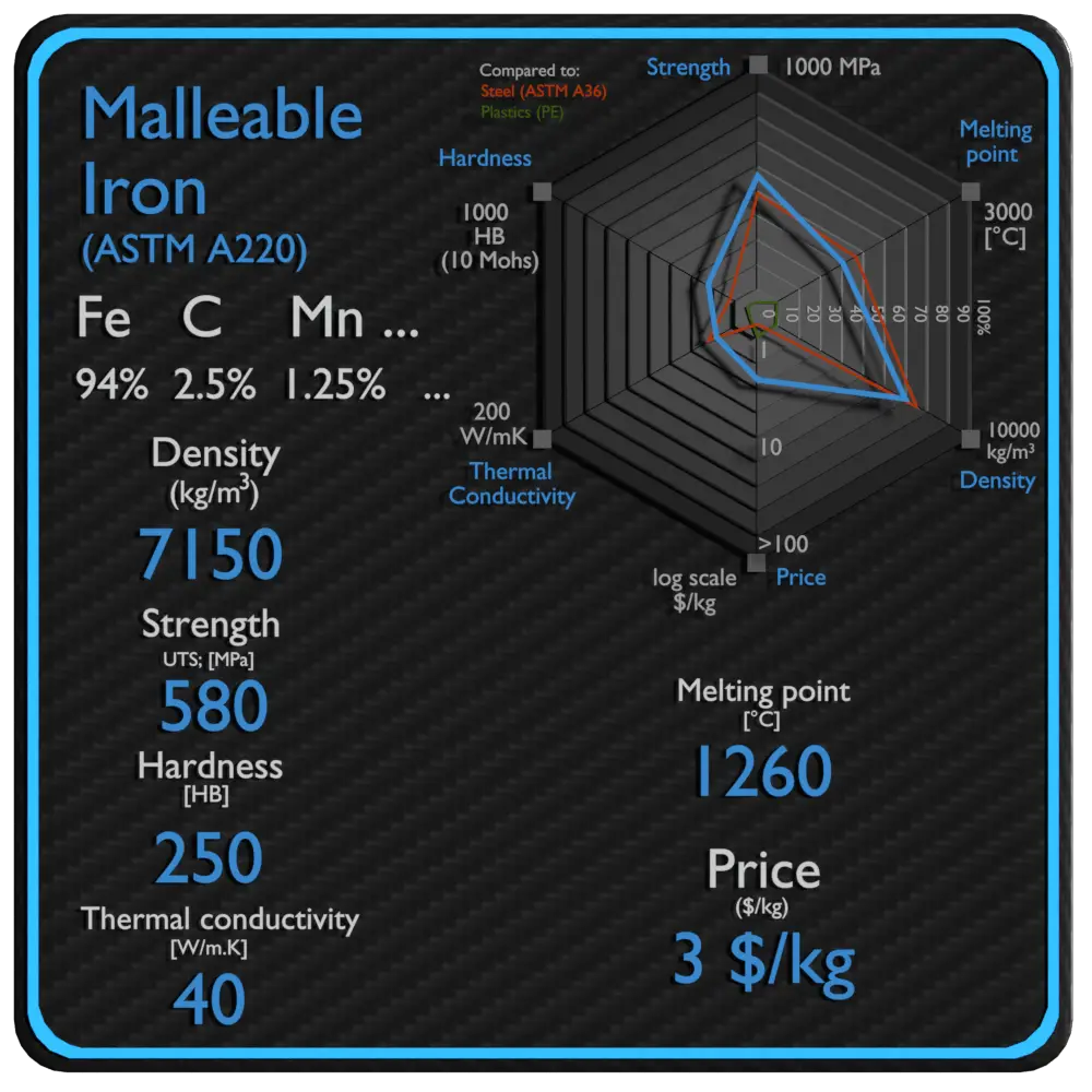
| Density | 8100 kg/m3 |
| Ultimate Tensile Strength | 445 MPa |
| Yield Strength | 280 MPa |
| Young’s Modulus of Elasticity | 135 GPa |
| Brinell Hardness | 200 BHN |
| Melting Point | 1687 °C |
| Thermal Conductivity | 12 W/mK |
| Heat Capacity | 505 J/g K |
| Price | 29 $/kg |
Density of Invar
Typical densities of various substances are at atmospheric pressure. Density is defined as the mass per unit volume. It is an intensive property, which is mathematically defined as mass divided by volume: ρ = m/V
In words, the density (ρ) of a substance is the total mass (m) of that substance divided by the total volume (V) occupied by that substance. The standard SI unit is kilograms per cubic meter (kg/m3). The Standard English unit is pounds mass per cubic foot (lbm/ft3).
Density of Invar is 8100 kg/m3.
Example: Density
Calculate the height of a cube made of Invar, which weighs one metric ton.
Solution:
Density is defined as the mass per unit volume. It is mathematically defined as mass divided by volume: ρ = m/V
As the volume of a cube is the third power of its sides (V = a3), the height of this cube can be calculated:
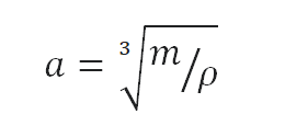
The height of this cube is then a = 0.498 m.
Density of Materials

Mechanical Properties of Invar
Strength of Invar
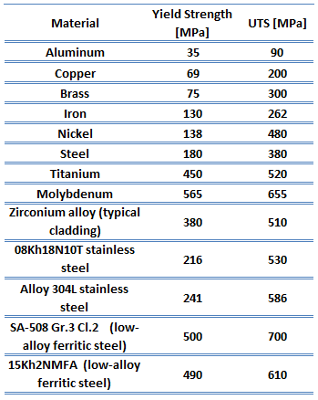
In mechanics of materials, the strength of a material is its ability to withstand an applied load without failure or plastic deformation. Strength of materials basically considers the relationship between the external loads applied to a material and the resulting deformation or change in material dimensions. In designing structures and machines, it is important to consider these factors, in order that the material selected will have adequate strength to resist applied loads or forces and retain its original shape.
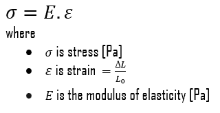
Strength of a material is its ability to withstand this applied load without failure or plastic deformation. For tensile stress, the capacity of a material or structure to withstand loads tending to elongate is known as ultimate tensile strength (UTS). Yield strength or yield stress is the material property defined as the stress at which a material begins to deform plastically whereas yield point is the point where nonlinear (elastic + plastic) deformation begins. In case of tensional stress of a uniform bar (stress-strain curve), the Hooke’s law describes behaviour of a bar in the elastic region. The Young’s modulus of elasticity is the elastic modulus for tensile and compressive stress in the linear elasticity regime of a uniaxial deformation and is usually assessed by tensile tests.
See also: Strength of Materials
Ultimate Tensile Strength of Invar
Ultimate tensile strength of Invar is 445 MPa.
Yield Strength of Invar
Yield strength of Invar is 280 MPa.
Modulus of Elasticity of Invar
The Young’s modulus of elasticity of Invar is 135 GPa.
Hardness of Invar
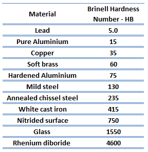
In materials science, hardness is the ability to withstand surface indentation (localized plastic deformation) and scratching. Brinell hardness test is one of indentation hardness tests, that has been developed for hardness testing. In Brinell tests, a hard, spherical indenter is forced under a specific load into the surface of the metal to be tested.
The Brinell hardness number (HB) is the load divided by the surface area of the indentation. The diameter of the impression is measured with a microscope with a superimposed scale. The Brinell hardness number is computed from the equation:
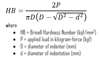
Brinell hardness of Invar is approximately 200 BHN (converted).
See also: Hardness of Materials
Example: Strength
Assume a plastic rod, which is made of Invar. This plastic rod has a cross-sectional area of 1 cm2. Calculate the tensile force needed to achieve the ultimate tensile strength for this material, which is: UTS = 445 MPa.
Solution:
Stress (σ) can be equated to the load per unit area or the force (F) applied per cross-sectional area (A) perpendicular to the force as:
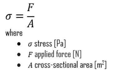
therefore, the tensile force needed to achieve the ultimate tensile strength is:
F = UTS x A = 445 x 106 x 0.0001 = 44 500 N
Strength of Materials

Elasticity of Materials

Hardness of Materials

Thermal Properties of Invar
Invar – Melting Point
Melting point of Invar is 1687 °C.
Note that, these points are associated with the standard atmospheric pressure. In general, melting is a phase change of a substance from the solid to the liquid phase. The melting point of a substance is the temperature at which this phase change occurs. The melting point also defines a condition in which the solid and liquid can exist in equilibrium. For various chemical compounds and alloys, it is difficult to define the melting point, since they are usually a mixture of various chemical elements.
Invar – Thermal Conductivity
Thermal conductivity of Invar is 12 W/(m·K).
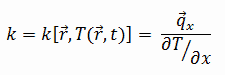
The heat transfer characteristics of a solid material are measured by a property called the thermal conductivity, k (or λ), measured in W/m.K. It is a measure of a substance’s ability to transfer heat through a material by conduction. Note that Fourier’s law applies for all matter, regardless of its state (solid, liquid, or gas), therefore, it is also defined for liquids and gases.
The thermal conductivity of most liquids and solids varies with temperature. For vapors, it also depends upon pressure. In general:

Most materials are very nearly homogeneous, therefore we can usually write k = k (T). Similar definitions are associated with thermal conductivities in the y- and z-directions (ky, kz), but for an isotropic material the thermal conductivity is independent of the direction of transfer, kx = ky = kz = k.
Invar – Specific Heat
Specific heat of Invar is 505 J/g K.
Specific heat, or specific heat capacity, is a property related to internal energy that is very important in thermodynamics. The intensive properties cv and cp are defined for pure, simple compressible substances as partial derivatives of the internal energy u(T, v) and enthalpy h(T, p), respectively:
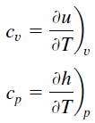
where the subscripts v and p denote the variables held fixed during differentiation. The properties cv and cp are referred to as specific heats (or heat capacities) because under certain special conditions they relate the temperature change of a system to the amount of energy added by heat transfer. Their SI units are J/kg K or J/mol K.
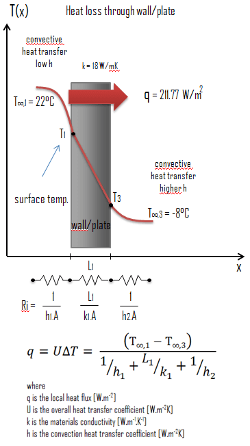
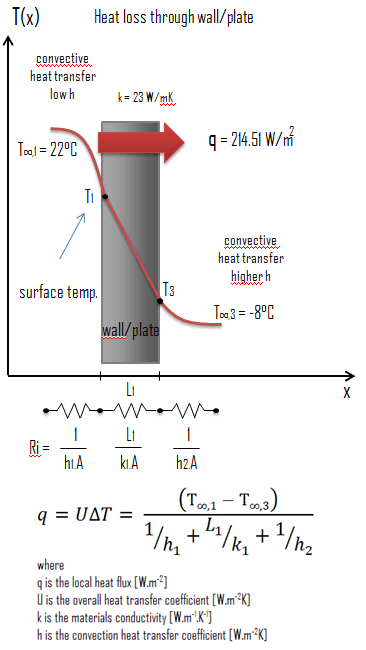
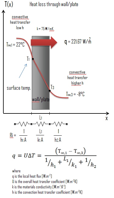
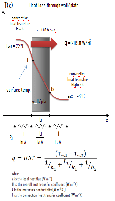
Example: Heat transfer calculation
 Thermal conductivity is defined as the amount of heat (in watts) transferred through a square area of material of given thickness (in metres) due to a difference in temperature. The lower the thermal conductivity of the material the greater the material’s ability to resist heat transfer.
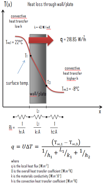
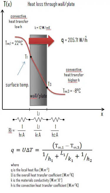
Calculate the rate of heat flux through a wall 3 m x 10 m in area (A = 30 m2). The wall is 15 cm thick (L1) and it is made of Invar with the thermal conductivity of k1 = 12 W/m.K (poor thermal insulator). Assume that, the indoor and the outdoor temperatures are 22°C and -8°C, and the convection heat transfer coefficients on the inner and the outer sides are h1 = 10 W/m2K and h2 = 30 W/m2K, respectively. Note that, these convection coefficients strongly depend especially on ambient and interior conditions (wind, humidity, etc.).
Calculate the heat flux (heat loss) through this wall.
Solution:
As was written, many of the heat transfer processes involve composite systems and even involve a combination of both conduction and convection. With these composite systems, it is often convenient to work with an overall heat transfer coefficient, known as a U-factor. The U-factor is defined by an expression analogous to Newton’s law of cooling:
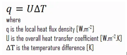
The overall heat transfer coefficient is related to the total thermal resistance and depends on the geometry of the problem.
Assuming one-dimensional heat transfer through the plane wall and disregarding radiation, the overall heat transfer coefficient can be calculated as:
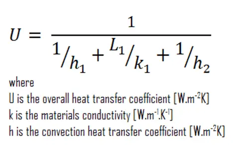
The overall heat transfer coefficient is then: U = 1 / (1/10 + 0.15/12 + 1/30) = 6.86 W/m2K
The heat flux can be then calculated simply as: q = 6.86 [W/m2K] x 30 [K] = 205.71 W/m2
The total heat loss through this wall will be: qloss = q . A = 205.71 [W/m2] x 30 [m2] = 6171.43 W
Melting Point of Materials

Thermal Conductivity of Materials

Heat Capacity of Materials